Non-overlapping graphical user interface workspace

a workspace and graphical technology, applied in the field of personal computer systems, can solve problems such as and achieve the effect of increasing the size of the object uni

Inactive Publication Date: 2005-06-09
IBM CORP
View PDF8 Cites 198 Cited by
  • Summary
  • Abstract
  • Description
  • Claims
  • Application Information

AI Technical Summary

Benefits of technology

[0011] In an alternative embodiment, when the system is in the non-overlapping mode, objects on the desktop are configured to have “sticky” borders, that is, as the border of a selected object comes into contact with the border of another object, the two objects adhere to each other as though they were glued together. This creates what is referred to herein as an “object unit” (two or more objects adhering to each other as a group), such that the two adhered objects now move in unison as a single unit. As the object unit is further moved, it may contact and adhere to additional objects as their borders collide, thus increasing the size of the object unit.

Problems solved by technology

As the object unit is further moved, it may contact and adhere to additional objects as their borders collide, thus increasing the size of the object unit.

Method used


Image

  • Non-overlapping graphical user interface workspace
  • Non-overlapping graphical user interface workspace
  • Non-overlapping graphical user interface workspace

Examples


Embodiment Construction

[0021] To better understand the present invention, it is helpful to observe the operation of the prior art. All of the examples below illustrate the present invention and the prior art in an environment wherein the objects displayed on the desktop are window objects. However, it is understood that the present invention is not limited to window objects and can function with any objects, including desktop icons; graphical objects in modeling tools, and the like.

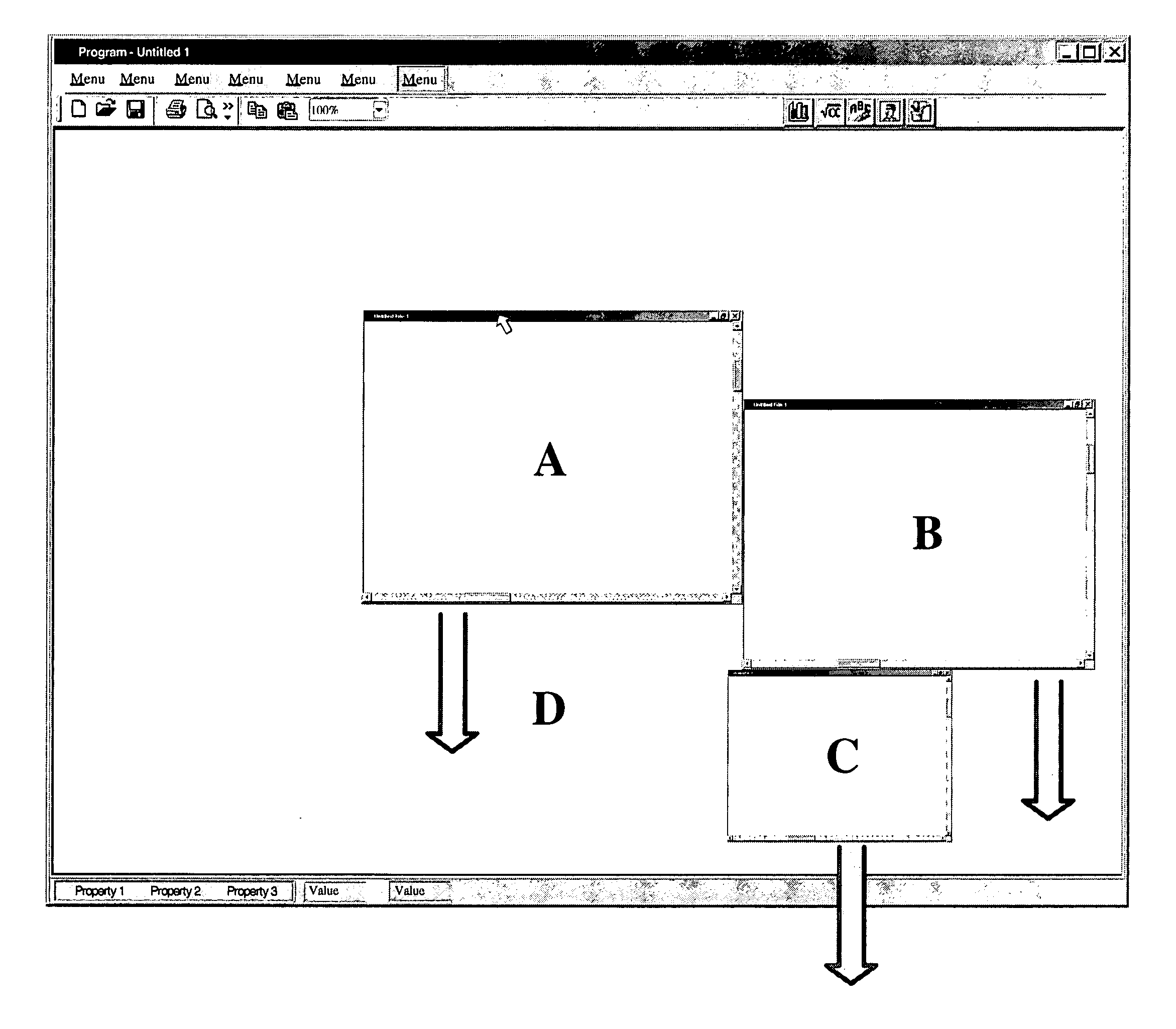
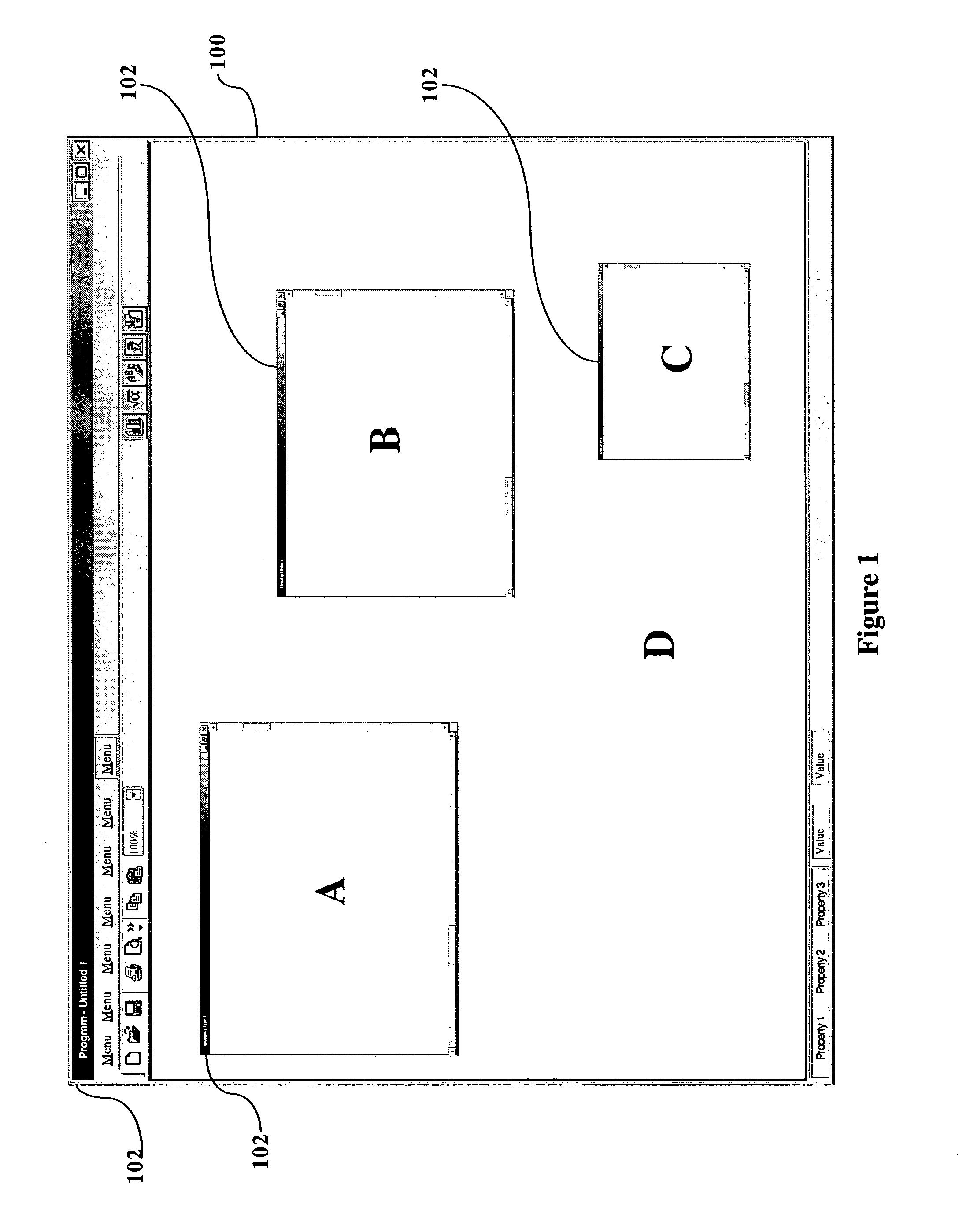
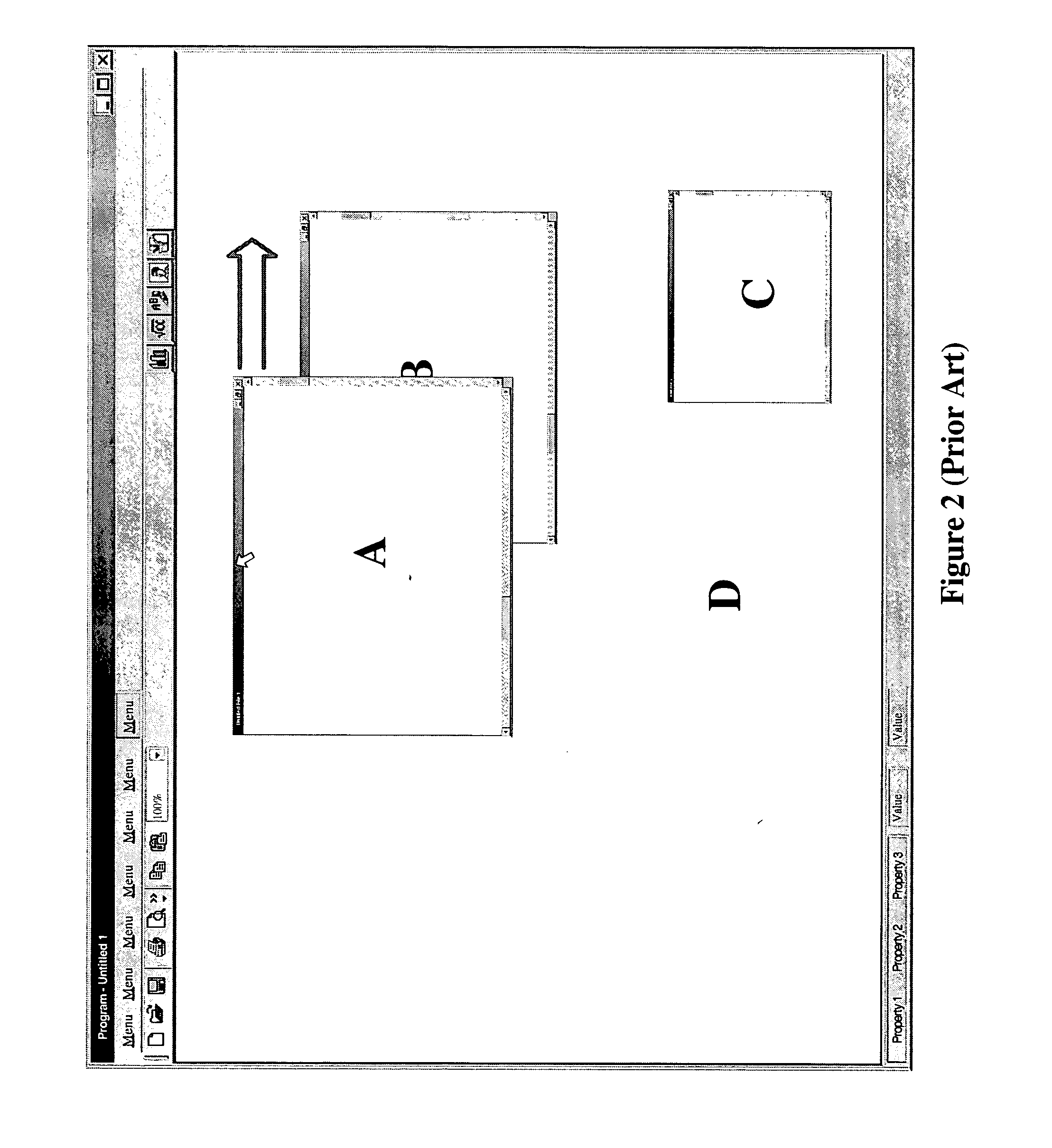
[0022]FIGS. 1 and 2 illustrate the operation, and deficiencies, of the prior art described above. FIG. 1 shows a typical desktop D, displayed within a GUI 100. Situated on the desktop are windows A, B, and C. Each window has a title bar 102 (as does desktop D), which is simply a graphical portion of the window where, typically, a title will be displayed, identifying the contents of the window.

[0023] The desktop D is a standard, overlapping desktop, where each window can overlap other windows. If a user wishes to move window A...


PUM


Abstract

A user interface mechanism that introduces a novel concept referred to as a “non-overlapping workspace”. A system user can switch between the traditional overlapping workspace and the novel non-overlapping workspace, depending upon how they wish to move and manage objects in the workspace. In the non-overlapping mode, as the user moves a selected object to relocate it within the work area, as its border touches another object, the selected object pushes the other object (rather than cover it). In an alternative embodiment, when the system is in the non-overlapping mode, objects on the desktop have “sticky” borders, that is, as the border of a selected object comes into contact with the border of another object, the two objects are coupled to each other as though they were glued together, forming an “object unit”.

Description

BACKGROUND OF THE INVENTION [0001] 1. Field of the Invention [0002] This invention relates to personal computer systems and, more particularly, to a method, system, and computer program product for improving a graphical user interface (GUI) on a personal computer system, and the use thereof. [0003] 2. Description of the Related Art [0004] In recent years, virtually all personal computers and workstations have adopted a graphical user interface (GUI) environment, which allows a user to manage and execute applications using a “point and click” method on objects shown on the computer display. The main GUI background is commonly referred to as the “desktop” or workspace, and “objects” are typically displayed on the desktop. These objects may include graphic icons, which represent a software application or function, and windows, which divide the viewable portion of the desktop into different areas (“sub-desktops”) in which details pertaining to a particular application or operation are d...

Claims


Application Information

Patent Timeline
Patent Type & Authority Applications(United States)
IPC IPC(8): G06F3/00G06F3/048
CPCG06F3/0481
Inventor GROTJOHN, D. KIRKHAYNES, THOMAS R.SALAHSHOOR, MOHAMAD R.SANTOS-GOMEZ, LUCINIO
Owner IBM CORP
Why Eureka
Try Eureka