
Ice tray and ice making machine, refrigerator both using the ice tray

a technology of ice tray and ice making machine, which is applied in the field of ice tray, can solve the problems that the cell b>2/b> is not heated enough and cannot evacuate ice smoothly, and achieve the effect of evacuating smoothly

Inactive Publication Date: 2005-06-16
PANASONIC CORP
View PDF9 Cites 71 Cited by
  • Summary
  • Abstract
  • Description
  • Claims
  • Application Information

AI Technical Summary

Benefits of technology

[0009] An ice tray of the present invention includes a tray section and a heater. The tray section has a first face and a second face opposite to the first face. The first face temporarily retains water and the water is cooled to make ice. The heater is formed on a side of the second face by unitary molding together with the tray section, and warms the tray section for the ice to come off the tray section. The unitary molding of the heater with the tray section stabilizes the solid contact between the tray section and the heater, so that respective cells are uniformly warmed. As a result, pieces of ice can be evacuated smoothly from the cells.

Problems solved by technology

Thus cell 2 not heated enough cannot evacuate ice smoothly.

Method used


Image

  • Ice tray and ice making machine, refrigerator both using the ice tray
  • Ice tray and ice making machine, refrigerator both using the ice tray
  • Ice tray and ice making machine, refrigerator both using the ice tray

Examples


Embodiment Construction

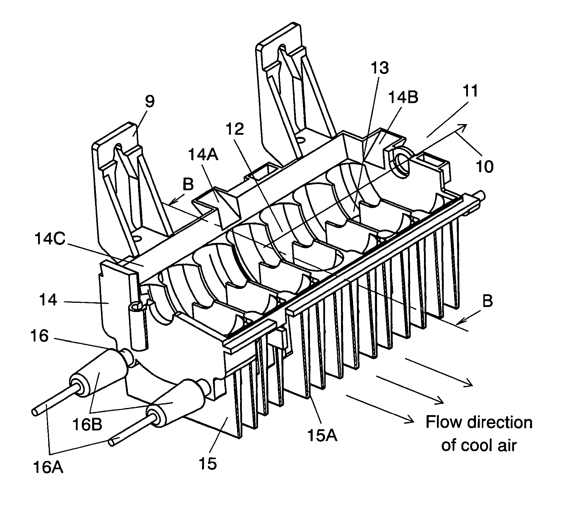
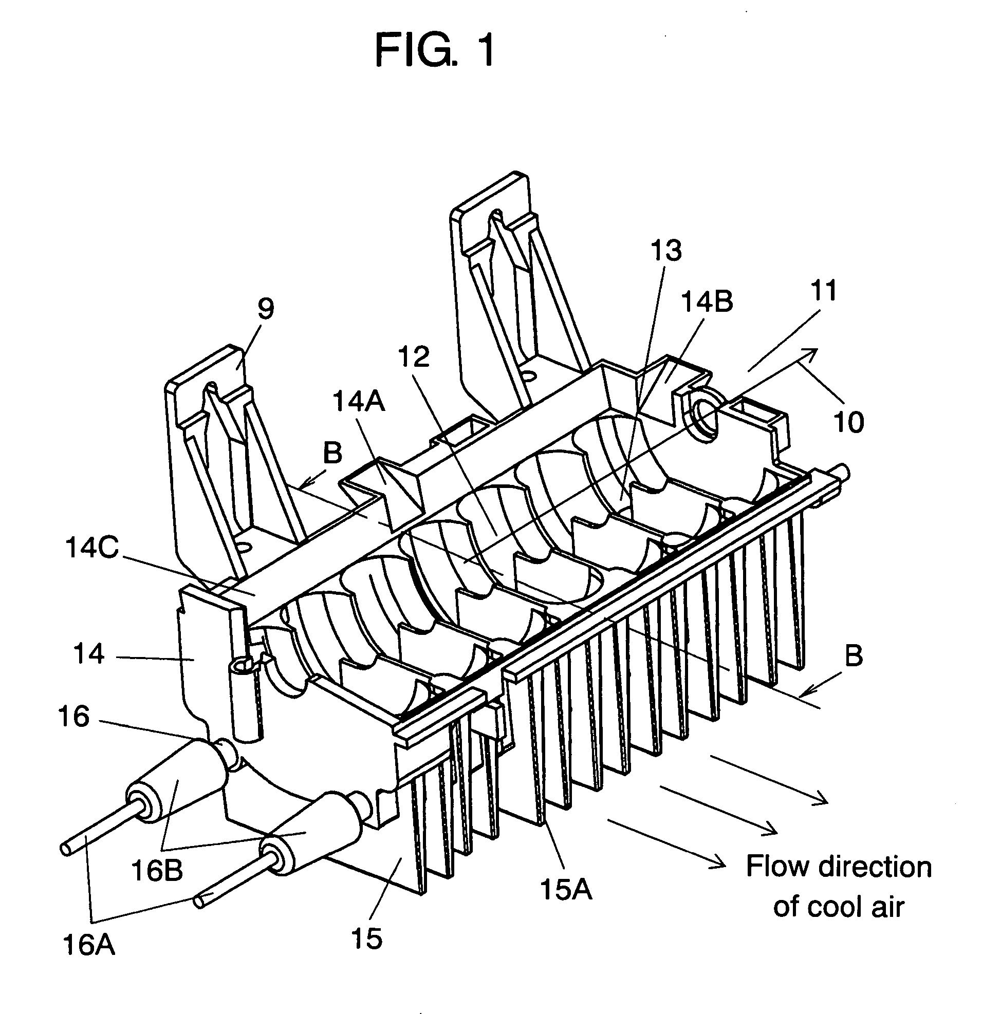
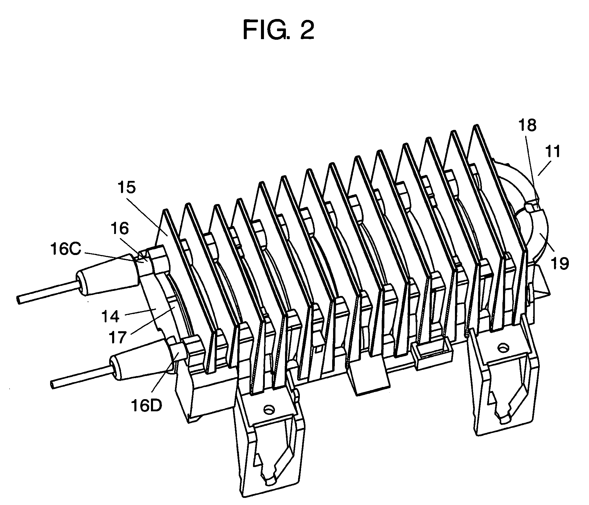
[0024]FIG. 1 shows a perspective view of an ice tray in accordance with an exemplary embodiment of the present invention. FIG. 2 shows a perspective view from a bottom side of the ice tray. FIG. 3 shows a sectional view of the ice tray taken along line 3-3.

[0025] Ice tray (hereinafter referred to simply as “tray”) 11 has tray section 14 and water inlets 14A and 14B through which water is poured from water-supply valve (not shown) to tray section 14. Tray section 14 includes a first face on which plural semicircular cells 12 are provided for retaining water temporarily, and groove 13 is disposed on a lateral wall of cells 12 adjacent to each other so that the water can run back and forth between adjacent cells 12. In other words, tray section 14 has major axis direction 10 and a minor axis direction substantially perpendicular to the major axis, and its top face shapes in approx. rectangle. The construction shown in FIGS. 1 and 2 includes seven cells aligned in line.

[0026] Tray sec...


PUM

PropertyMeasurementUnit
Flow rateaaaaaaaaaa
Shapeaaaaaaaaaa
Areaaaaaaaaaaa

Abstract

An ice tray includes a tray section and a heater. The tray section has a first face and a second face opposite to the first face. The first face temporarily retains water and the water is cooled to make ice. The heater is unitarily molded with the tray section at the second face, and warms the tray section for the ice to come off the tray section.

Description

BACKGROUND OF THE INVENTION [0001] 1. Field of the Invention [0002] The present invention relates to an ice tray placed, for example, in a freezing compartment of an refrigerator and making ice by cooling the water poured therein, it also relates to an ice making machine and a refrigerator both using the same ice tray. [0003] 2. Background Art [0004] A conventional ice tray placed in a freezing compartment of a refrigerator is disclosed, e.g. Japanese Patent Unexamined Publication No. 2001-272146, and the entire ice tray is made from aluminum. This conventional ice tray is described hereinafter with reference to FIGS. 12 and 13. FIG. 12 shows a perspective view of the conventional ice tray, and FIG. 13 shows a sectional view taken along line 13-13 shown in FIG. 12. [0005] Ice tray 1 (hereinafter referred to simply as “tray”) is made from aluminum alloy excellent in heat conductivity. Tray 1 includes plural cells 2 which temporarily retain water. Groove 3 rests between cells 2 adjace...

Claims


Application Information

Patent Timeline
IPC IPC(8): F25C1/24F25C5/08
CPCF25C1/24F25D2400/04F25C5/08
Inventor SHOUKYUU, MASATOSHITSUJIMOTO, AKINORIONISHI, ICHIROADACHI, TADASHITATSUI, HIROSHIISHITA, MITOKO
Owner PANASONIC CORP
Features
  • Generate Ideas
  • Intellectual Property
  • Life Sciences
  • Materials
  • Tech Scout
  • Unparalleled Data Quality
  • Higher Quality Content
  • 60% Fewer Hallucinations
Learn More