
Tip shaping apparatus

a tip shaping and tip technology, applied in the direction of electrode features, manufacturing tools, electrode maintenance, etc., can solve the problems of welding failure, damage to the workpiece, etc., and achieve the effect of preventing wobbling of the electrode tip, facilitating the removal of burrs, and facilitating cutting and removing burrs

Inactive Publication Date: 2012-07-24
KYOKUTOH +1
View PDF17 Cites 2 Cited by
  • Summary
  • Abstract
  • Description
  • Claims
  • Application Information

AI Technical Summary

Benefits of technology

The apparatus effectively shapes electrode tips into reusable condition, preventing burr engagement with workpieces and ensuring reliable welding by removing burrs, thus enhancing production efficiency and preventing welding failures.

Problems solved by technology

If the electrode tip is used for welding while having a burr thereon, the burr is likely to engage with a vertical wall section of a workpiece proximate the welding area and damage the workpiece.
Moreover, if the burr contacts the workpiece, an electric current for welding passes through the burr in a furcate manner, which precludes a desired welding and causes welding failure.

Method used


Image

  • Tip shaping apparatus
  • Tip shaping apparatus
  • Tip shaping apparatus

Examples


Embodiment Construction

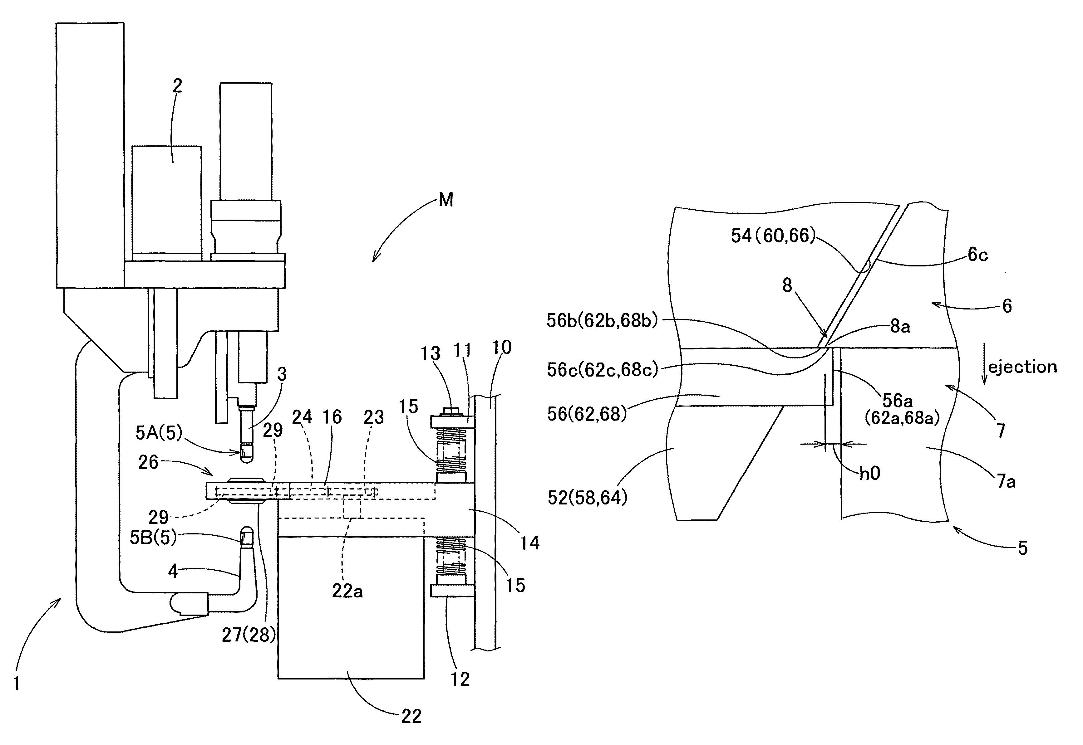
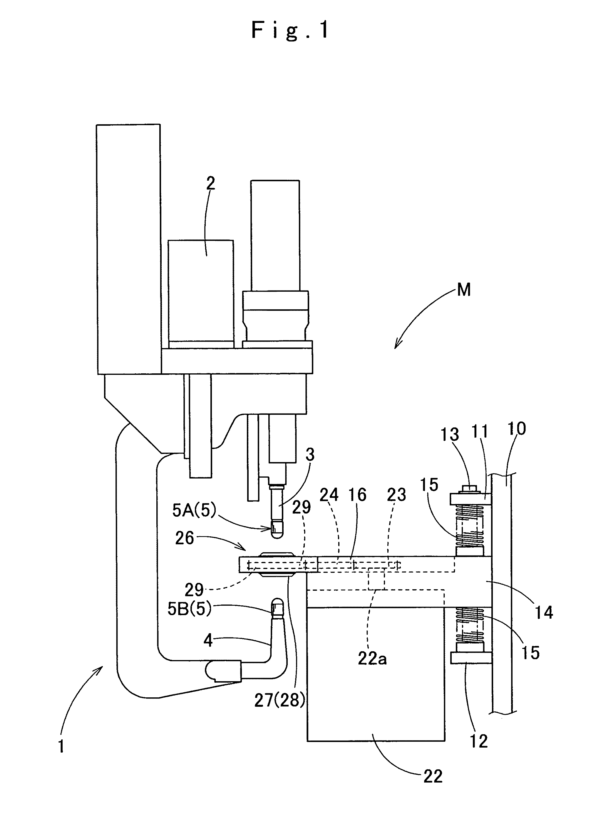
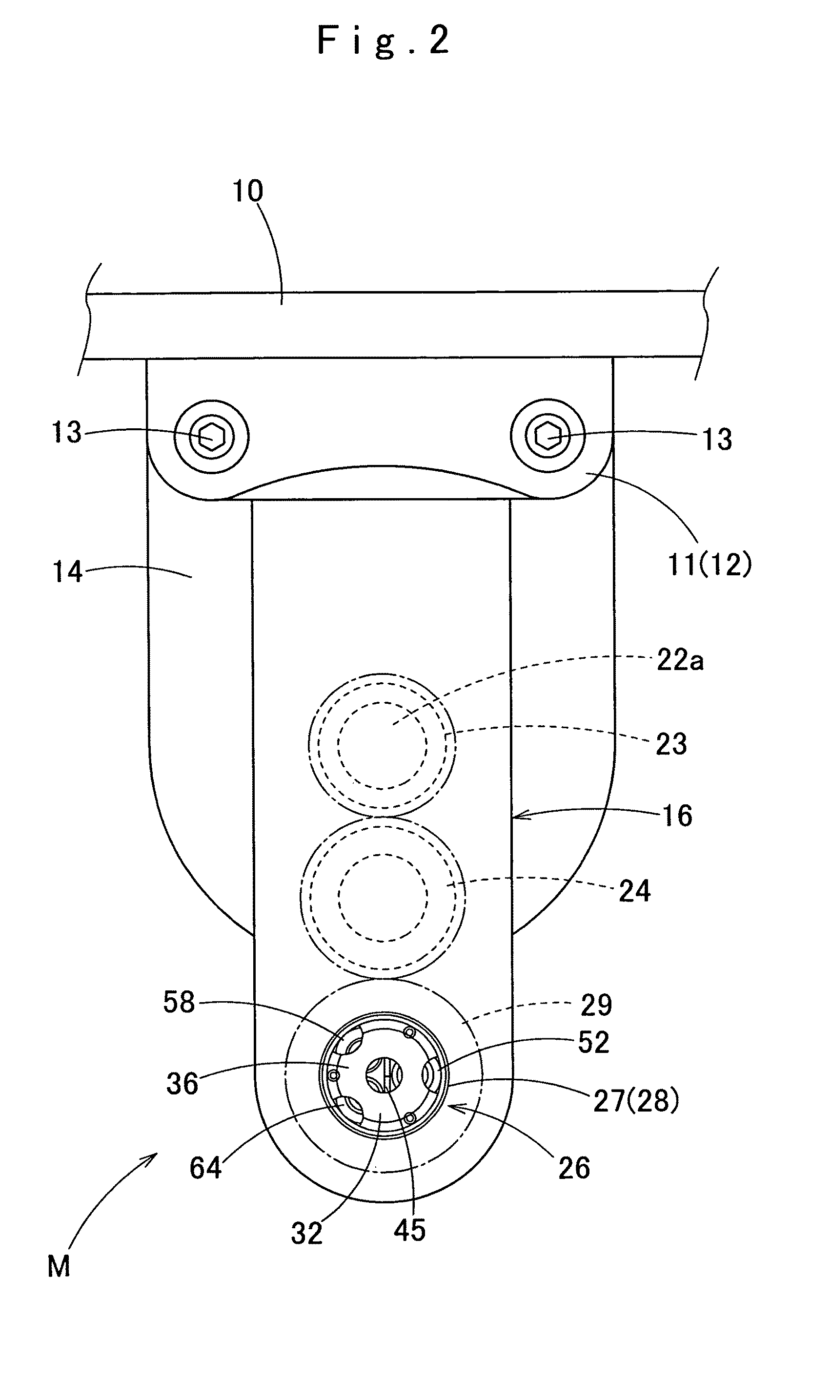
[0070]An embodiment of the present invention is described below with reference to the accompanying drawings. As shown in FIGS. 1 and 3, a tip shaping apparatus M embodying the invention is used for forming and shaping a pair of electrode tips 5 (5A, 5B) fitted in shanks 3 and 4 of a welding gun 1. The welding gun 1 is a servo gun held at the leading end of an arm of an unillustrated multi-joint welding robot. The servo gun 1, being general-purpose, holds the electrode tips 5A and 5B movably by a servo motor 2 having an encoder and has a position control function that approximates the tips 5A and 5B to each other. The servo gun 1 also has an arithmetic function that enables control of number of revolutions and torque control of the servo motor 2 as well as position control, welding force control or the like of the electrode tips 5A and 5B.

[0071]Each of the electrode tips 5A and 5B includes a tip section 6 for contact with a workpiece to be welded and a root section 7 which is columna...


PUM

PropertyMeasurementUnit
diameteraaaaaaaaaa
diameteraaaaaaaaaa
diameteraaaaaaaaaa

Abstract

A tip shaping apparatus presses electrode tips against a shaping roller thereof held by a rotationally driven holder in such a manner as to bring tip sections of the tips close to each other, thereby shaping the tip sections into reusable condition. The tip shaping apparatus includes deburring sections located in such positions as to confront burrs that are formed during shaping in such a manner as to project from outer circumferences of root sections proximate the tip sections of the electrode tips in a direction perpendicular to the axes of the electrode tips, at ejection of the electrode tips from the apparatus. Each of the deburring sections is located proximate an outer circumferential plane of the root section of each of the electrode tips undergoing shaping so as to abut against and cut off or bend the burrs in such a manner as to suppress the projecting height of the burrs when the electrode tips are ejected from the tip shaping apparatus.

Description

CROSS REFERENCE TO RELATED APPLICATIONS[0001]This application is a U.S. national stage application of PCT / JP2009 / 064975 filed on Aug. 27, 2009, and claims priority to, and incorporates by reference, Japanese Patent Application No. 2008-223969 filed on Sep. 1, 2008.TECHNICAL FIELD[0002]The present invention relates to a tip shaping apparatus that forms and shapes a pair of electrode tips carried by a welding gun for use in spot welding while producing as less grinding swarf as possible, and more particularly, to a tip shaping apparatus that removes burrs produced on the electrode tips during shaping.BACKGROUND[0003]Frequent use of electrode tips for use in spot welding or the like causes deformation of tip sections of the electrode tips, thereby compelling stopping of welding operation. A tip shaping apparatus is known in Patent Literature 1 shaping electrode tips into reusable condition by applying plastic deformation to deformed tip sections of electrode tips rather than by cutting...

Claims


Application Information

Patent Timeline
Patent Type & Authority Patents(United States)
IPC IPC(8): B23B5/16
CPCB23K11/115B23K11/3063Y10T409/3042Y10T409/304256Y10T29/5182
Inventor TEZAWA, KAZUHIRONIWA, TAKANORI
Owner KYOKUTOH
Features
  • Generate Ideas
  • Intellectual Property
  • Life Sciences
  • Materials
  • Tech Scout
  • Unparalleled Data Quality
  • Higher Quality Content
  • 60% Fewer Hallucinations
Learn More