Screw

a screw and screw body technology, applied in the field of screws, can solve the problems of laborious screwing operation, increased drilling resistance, and worsened screwing efficiency, and achieve the effect of enhancing screwing efficiency and reducing drilling resistan

Active Publication Date: 2019-04-11
TAIWAN SHAN YIN INT CO LTD
View PDF19 Cites 0 Cited by
  • Summary
  • Abstract
  • Description
  • Claims
  • Application Information

AI Technical Summary

Benefits of technology

[0004]The object of this invention is to provide a screw capable of reducing the drilling resistance to enhance the screwing efficiency.

Problems solved by technology

Meanwhile, the conventional fastener 1 keeps pressing the fibers while screwing into the object 2 to result in the enhanced drilling resistance and worsened screwing efficiency.
The accumulated cut chips cause the laborious screwing operation when the conventional fastener 1 keeps screwing into the object 2.
Furthermore, the object 2 may crack when the conventional fastener 1 keeps moving downwards and squeezing the accumulated cut chips.

Method used


Image

  • Screw
  • Screw
  • Screw

Examples


Embodiment Construction

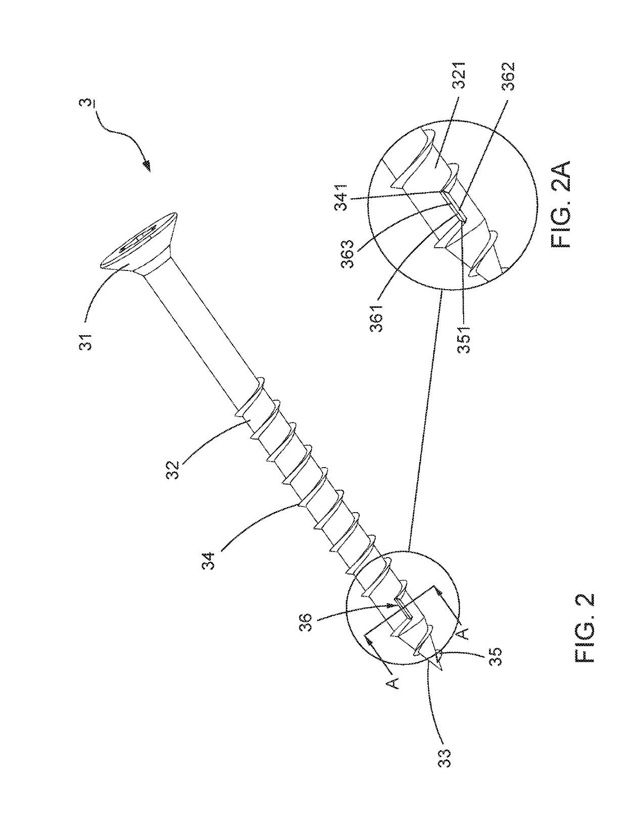
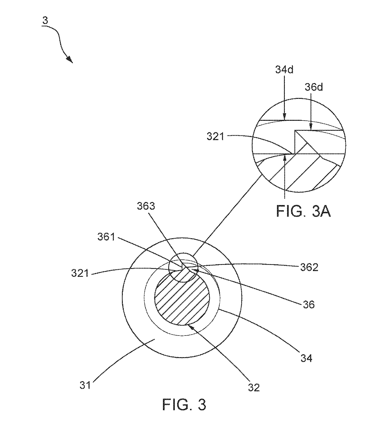
[0025]Referring to FIG. 2, a first preferred embodiment of a screw 3 of this invention is disclosed. The screw 3 includes a head 31, a shank 32 extending downwards from the head 31, a drilling portion 33 fitted at an end of the shank 32 and opposite to the head 31, a first threaded section 34 spiraled on the shank 32, and a leading threaded section 35 helically extending upwards from the drilling portion 33. The first threaded section 34 and the leading threaded section 35 are separated from each other to define a valley 321 between the first threaded section 34 and the leading threaded section 35. Referring to FIG. 2A, in the preferred embodiments, the first threaded section 34 is continuously disposed around the shank 32 and terminates at a first end 341, and the leading threaded section 35 is helically disposed on the length of the drilling portion 33 and terminates at a second end 351. The second end 351 may be located on the drilling portion 33 or on the shank 32. The valley 32...


PUM

PropertyMeasurementUnit
heightaaaaaaaaaa
drilling resistanceaaaaaaaaaa
frictionaaaaaaaaaa

Abstract

A screw includes a shank, a head connected thereto, a drilling portion opposite to the head, a first threaded section spirally formed on the shank, and a leading threaded section spirally extending upwards from the drilling portion. The two threaded section are disconnected so that a valley is formed between them. At least one cutting unit protrudes from the valley and has two ends connected to the first threaded section and the leading threaded section respectively. The leading threaded section assists the drilling portion in cutting and drilling into an object while screwing, and the cutting unit protruding from the valley severs fibers which are not cut by the leading threaded section completely to prevent the entanglement of the fibers. The valley helps accommodate and evacuate cut chips. Therefore, the drilling resistance is reduced effectively to increase the screwing efficiency.

Description

BACKGROUND OF THE INVENTION1. Field of the Invention[0001]This invention relates to a screw and relates particularly to a screw capable of increasing the screwing efficiency.2. Description of the Related Art[0002]Referring to FIG. 1, a conventional fastener 1 comprises a head 11, a shank 12 extending downwards from the head 11, a drilling portion 13 connected to an end of the shank 12, and a threaded section 14 spirally disposed on the shank 12. During the screwing operation, a driving tool (not shown) is applied to rotate the head 11 to allow the drilling portion 13 which is rendered to touch a surface of an object 2 to start drilling. Simultaneously, the drilling portion 13 drives the threaded section 14 to move downwards. When the threaded section 14 contacts the object 2, the threaded section 14 starts cutting the object 2 to thread the shank 12 into the object 2 to complete the screwing operation of the conventional fastener 1.[0003]During the screwing operation of the conventi...

Claims


Application Information

Patent Timeline
Patent Type & Authority Applications(United States)
IPC IPC(8): F16B25/10F16B25/00
CPCF16B25/103F16B25/0052F16B25/0015F16B25/0057F16B25/0089
Inventor SU, KOU-TSAIRSU, YU-JUNG
Owner TAIWAN SHAN YIN INT CO LTD
Why Eureka
Try Eureka