
Radius endmill

a technology of endmill and radius, which is applied in the direction of metal-working equipment, metal-working apparatus, milling equipment, etc., can solve the problems of increasing the dependency on electric discharge machining, difficulty in cutting operation, and chattering problems, and achieves the effect of improving the durability of the tool

Active Publication Date: 2010-04-20
OSG +1
View PDF6 Cites 4 Cited by
  • Summary
  • Abstract
  • Description
  • Claims
  • Application Information

AI Technical Summary

Benefits of technology

This design reduces cutting resistance, enhances tool durability, facilitates smooth chip evacuation, and prevents tool breakage and surface defects, enabling eco-friendly cutting operations with improved machining efficiency.

Problems solved by technology

However, an increase in a required depth of cut and the consequent increase in an overhang length of a cutting tool make it difficult to perform the cutting operation, thereby increasing dependency on the electric discharge machining.
Further, where the tool overhang length is large, a large number of revolutions of the cutting tool is likely to cause a chattering problem.
Thus, conventionally, there has not been expected a high performance of a cutting operation in a die mold machining.
Therefore, in the conventional radius endmill in which each bottom cutting edge 4 and each rounded corner cutting edge 5 receive a large load during the cutting operation, there is limitation as to improvement in durability of the cutting tool.
Where such a cutting operation performed with the considerably increased feed amount is a deep milling operation, all the produced chips are not likely to be evacuated from each flute of the endmill, so that some of the produced chips remaining in each flute could interfere each cutting edge and the workpiece, thereby causing risks of breakage of the endmill and defectiveness of a machined surface of the workpiece.
Further, for facilitating evacuation of the chips, there is necessity of use of cutting fluid, which could induce an environmental problem.

Method used


Image

  • Radius endmill
  • Radius endmill
  • Radius endmill

Examples


Embodiment Construction

[0015]Hereinafter, there will be described embodiments of the present invention, with reference to the drawings.

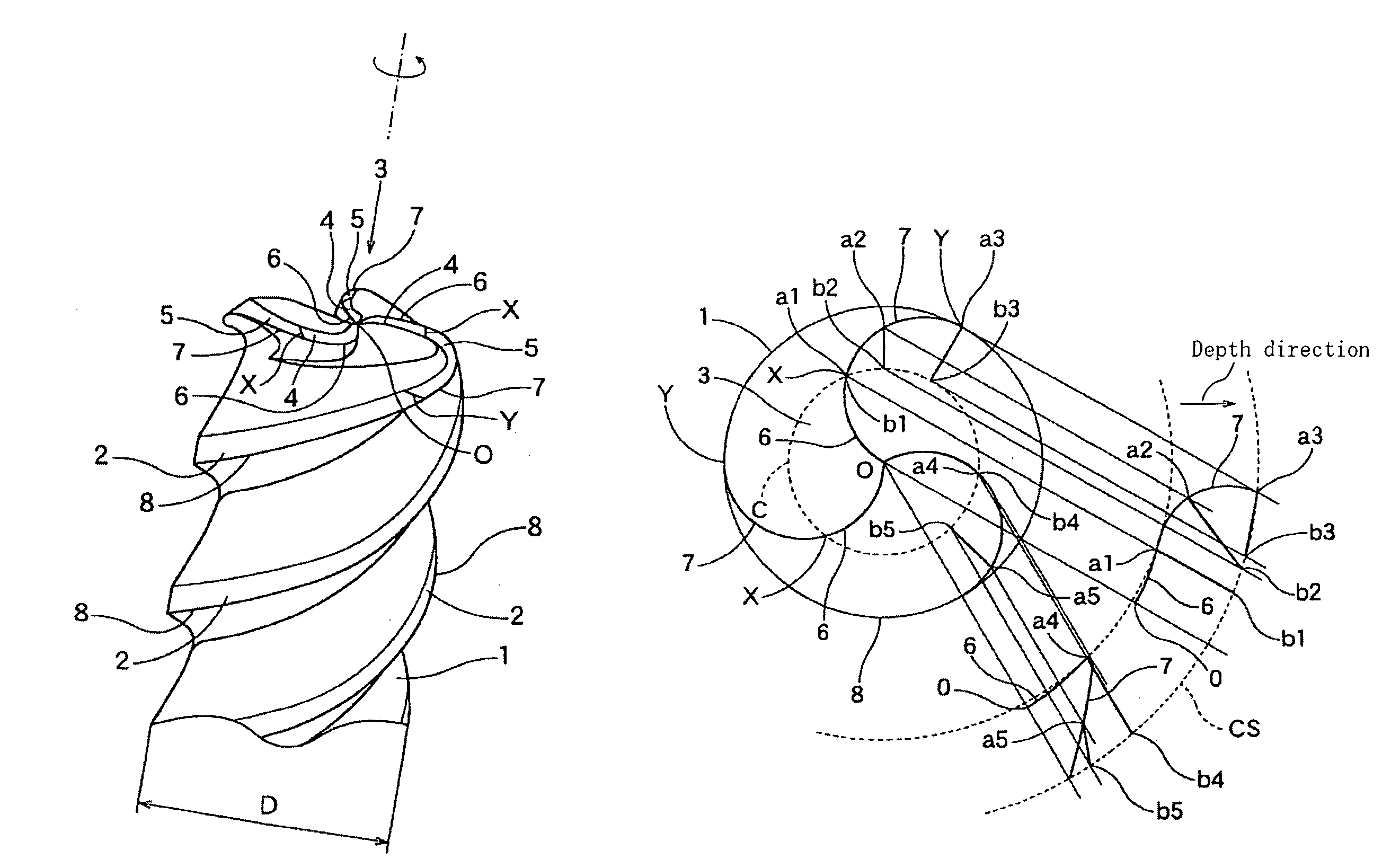
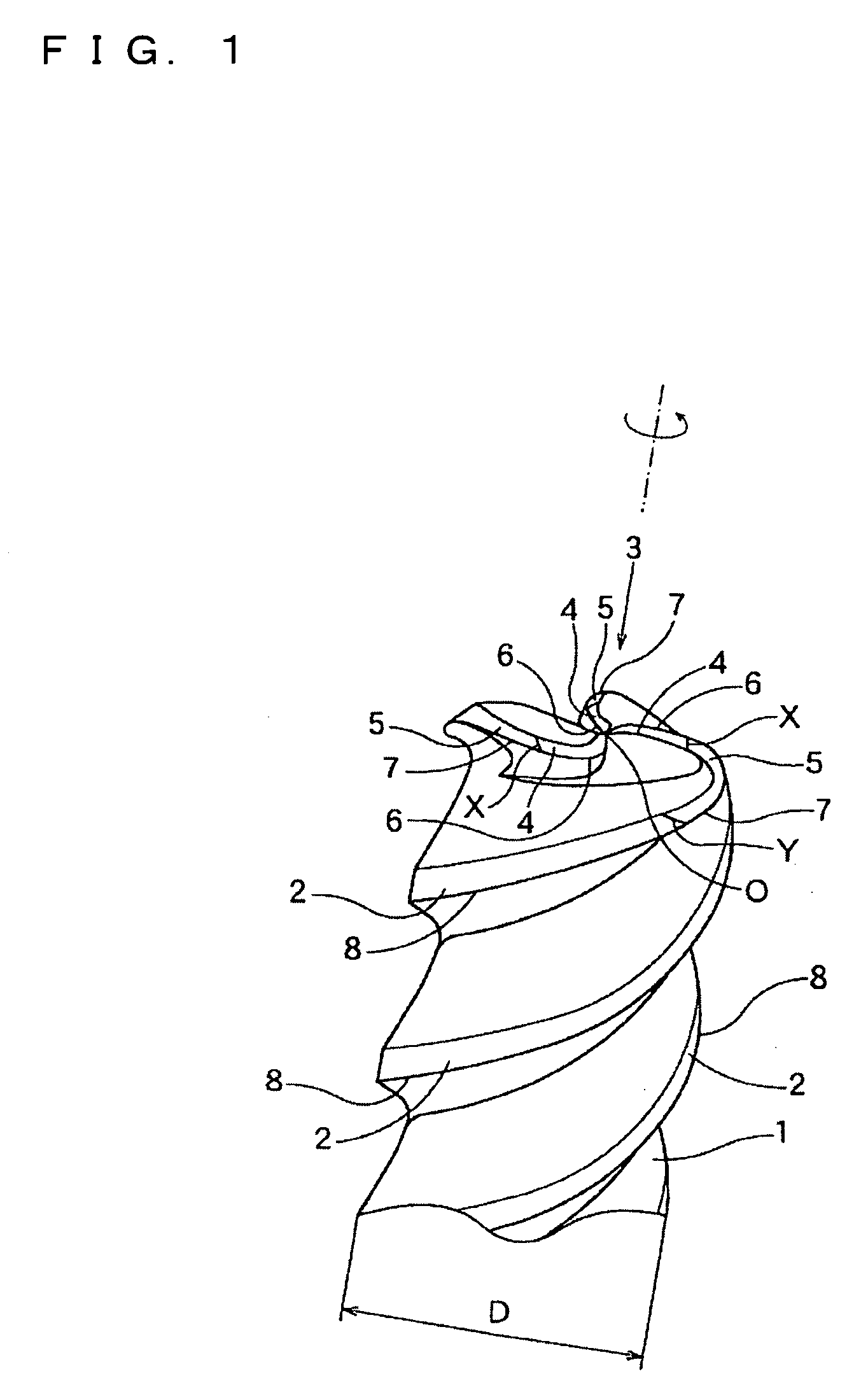
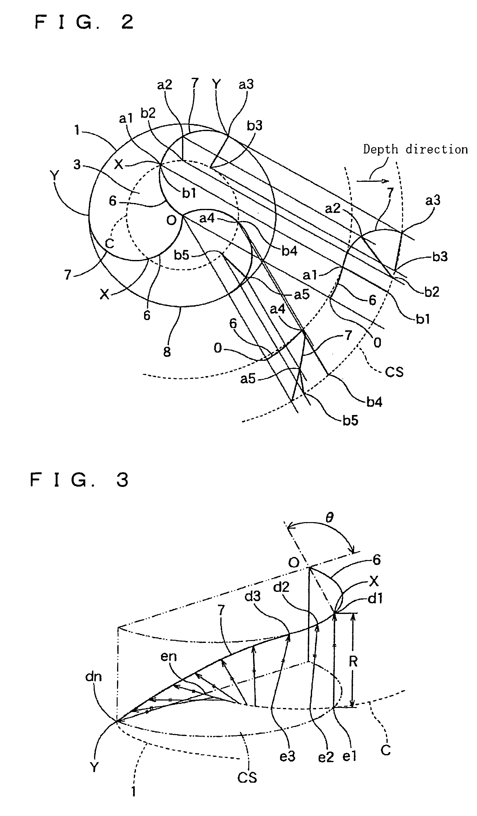
[0016]FIG. 1 is a perspective view showing a major portion of a three-tooth (three-flute) radius endmill constructed according to an embodiment of the invention. FIG. 2 is a view for explaining bottom cutting edges and rounded corner cutting edges of the radius endmill. FIG. 3 is a view for explaining each rounded corner cutting edge of the radius endmill. FIG. 4 is a view for explaining effects of the radius endmill. FIG. 5 is a perspective view of a chip produced when the radius endmill is used. FIG. 6 is a view for explaining bottom cutting edges and rounded corner cutting edges of a three-tooth radius endmill according to a modification of the embodiment. FIG. 7 is a view for explaining bottom cutting edges and rounded corner cutting edges of a two-tooth (two-flute) radius endmill according to another embodiment. FIG. 8 is a view for explaining bottom cutting edges and...


PUM


Abstract

A radius endmill has a peripheral cutting edge, a bottom cutting edge, and a rounded corner cutting edges whose ridge line is defined by a circular arc having a given radius as measured in a side view of the endmill that is parallel to the axis. The rounded corner cutting edge is located in a corner portion of the endmill in which the outer peripheral and the axial end intersect each other such that the peripheral cutting edge and the bottom cutting edge are connected to each other through the rounded corner cutting edge. The bottom cutting edge has a radially inner end lying at the axis, and a radially outer end at which the bottom cutting edge is connected to the rounded corner cutting edge. The bottom cutting edge is curved such that its ridge line is defined by a circular arc as seen in a plan view of the endmill that is perpendicular to the axis.

Description

TECHNICAL FIELD[0001]The present invention relates to a radius endmill, and more particularly to such a radius endmill which is used for performing a die mold machining, i.e., for machining a three-dimensional curved surface of a product (such as fording die, press die, die casting mold and resin forming die) in a machine tool, and which has a substantially cylindrical shape as a whole and includes rounded corner cutting edges (substantially arcuate shaped cutting edges) formed in a corner portion at which its peripheral cutting edges are connected to its bottom cutting edges.BACKGROUND ART[0002]For reducing a manufacturing time and an environmental problem in a die mold machining, it is preferable that the die mold machining is performed by a numerically-controlled cutting machine tool as much as possible, rather than by an electric discharge machining that requires a long machining time and an electrolyte. However, an increase in a required depth of cut and the consequent increase...

Claims


Application Information

Patent Timeline
Patent Type & Authority Patents(United States)
IPC IPC(8): B23C5/10
CPCB23C5/10B23C2210/0435B23C2210/084Y10T407/1948Y10T407/196Y10T407/1962Y10T407/1946B23C2210/202B23C5/00
Inventor AOKI, WATARU
Owner OSG
Features
  • Generate Ideas
  • Intellectual Property
  • Life Sciences
  • Materials
  • Tech Scout
  • Unparalleled Data Quality
  • Higher Quality Content
  • 60% Fewer Hallucinations
Learn More