Remote control fluid regulation system

a fluid regulation system and remote control technology, applied in mechanical equipment, valves, respirators, etc., can solve problems such as the inability to automatically regulate the flow of fluids, and achieve the effect of excluding automatic means

Inactive Publication Date: 2005-06-16
REMCORE
View PDF16 Cites 27 Cited by
  • Summary
  • Abstract
  • Description
  • Claims
  • Application Information

AI Technical Summary

Problems solved by technology

Typically, the system excludes any means for automatically adjusting the rate of fluid flow from the source through the tube to the site.

Method used

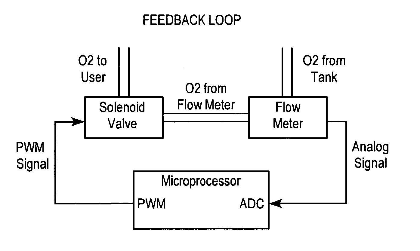
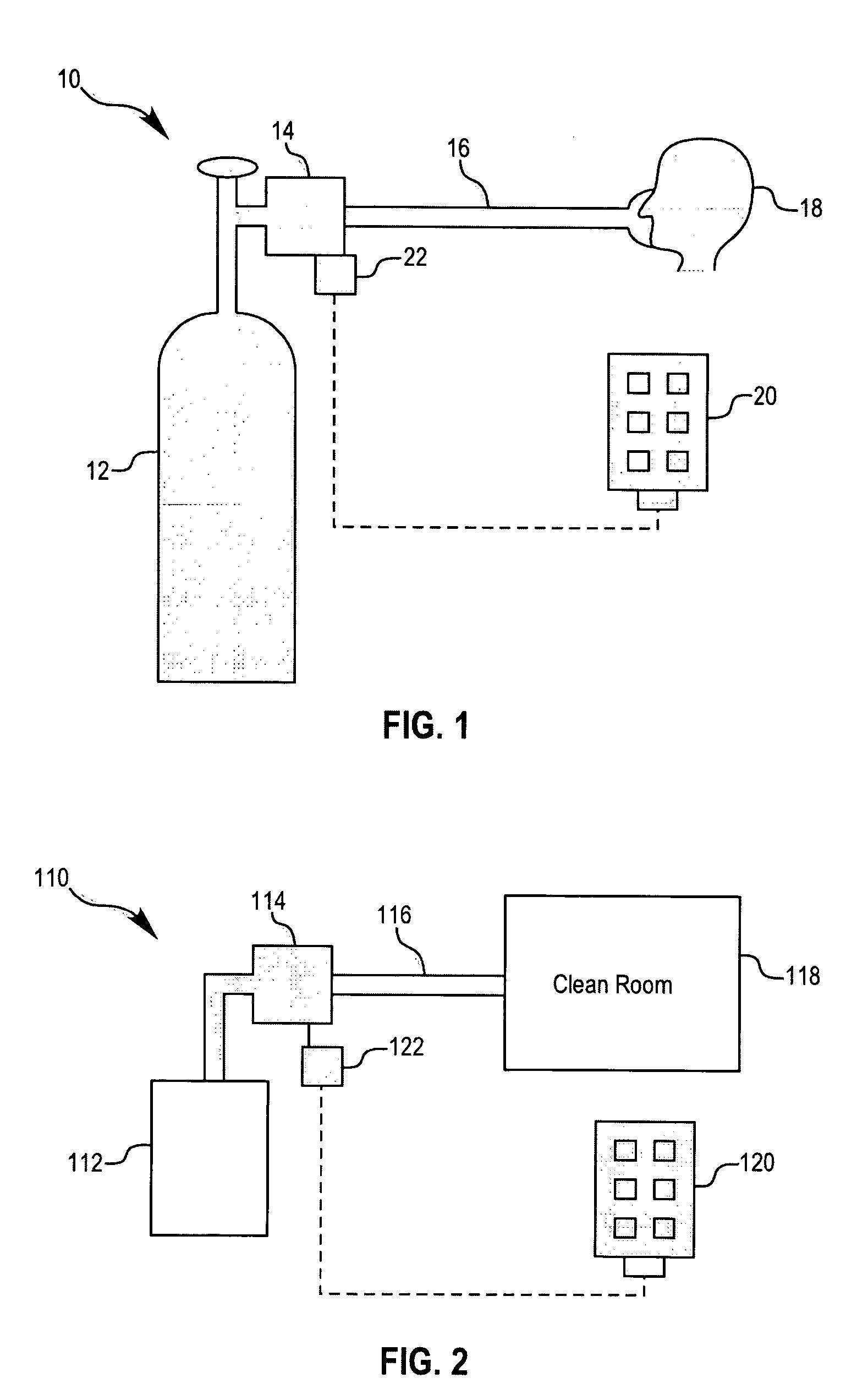
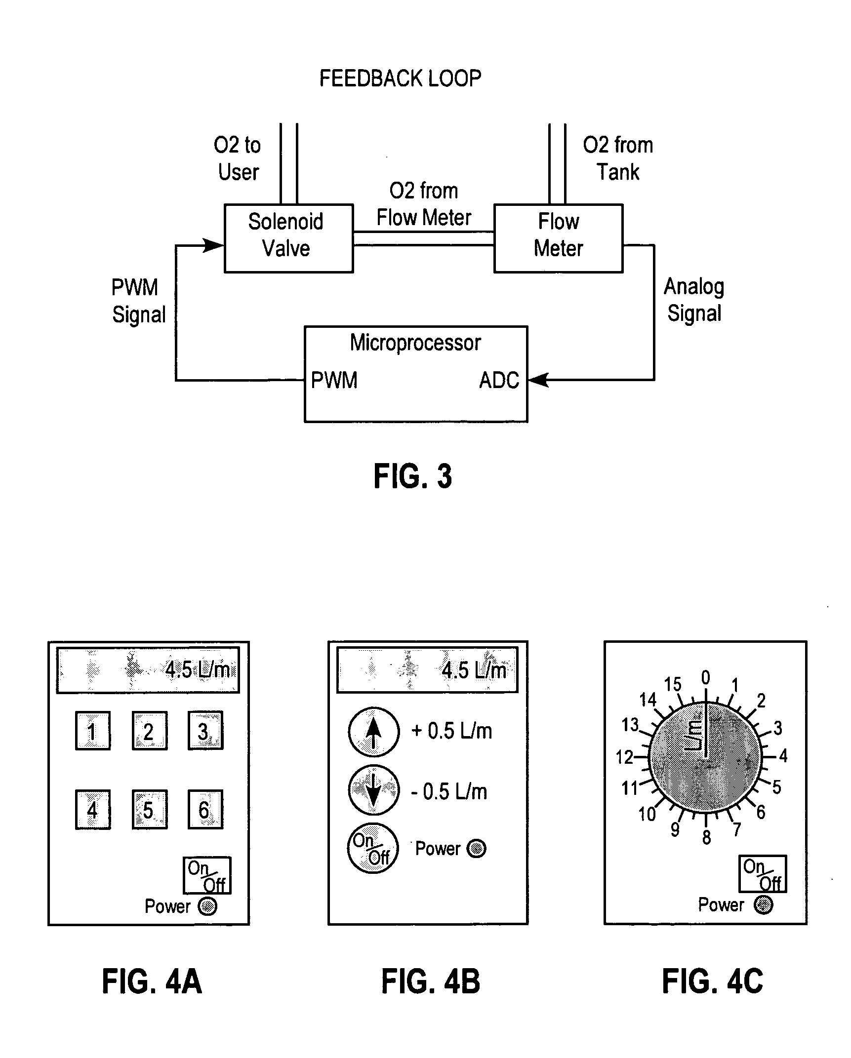

Image

  • Remote control fluid regulation system
  • Remote control fluid regulation system
  • Remote control fluid regulation system

Examples


Embodiment Construction

[0024] Before the invention is described in detail, it is to be understood that, unless otherwise indicated, this invention is not limited to particular materials, components or manufacturing processes, as such may vary. It is also to be understood that the terminology used herein is for purposes of describing particular embodiments only, and is not intended to be limiting.

[0025] As used in the specification and the appended claims, the singular forms “a,”“an” and “the” include plural referents unless the context clearly dictates otherwise. Thus, for example, reference to “remote control unit” includes a single remote control unit as well as a plurality of remote control units, reference to “an inlet” includes a single inlet as well as multiple inlets, and reference to “a valve” includes a single valve as well as an assembly of valves, and the like.

[0026] In this specification and in the claims that follow, reference will be made to a number of terms that shall be defined to have ...


PUM


Abstract

A fluid regulation system is provided comprising a source of a fluid, a tube in communication with the source for delivering the fluid from the source to a site, and a valve for controlling the rate of fluid flow from the source to the site. A remote control unit for controlling the valve is also provided to allow the user to adjust the rate of fluid flow from the source through the tube to the site. Typically, the system excludes any means for automatically adjusting the rate of fluid flow from the source through the tube to the site. The invention is particularly useful when the valve is out of the user's reach. Also provided is a method for delivering of a fluid to a site.

Description

CROSS-REFERENCE TO RELATED APPLICATIONS [0001] This is a continuation-in-part of U.S. patent application Ser. No. 10 / 714,467, filed Nov. 14, 2003, which is hereby incorporated by reference.TECHNICAL FIELD [0002] The invention relates generally to a fluid regulation system for regulating and delivering fluids from a source via a valve to a site. In particular, the invention relates to such a system for delivering a fluid to a remote site by means of a remote control unit. There may be a need to regulate levels of such fluids as inert gases, e.g., nitrogen, argon, in a clean room, or to regulate oxygen flow into an oxygen-rich environment. There may also be a need to control the level of toxic fluids, e.g., chlorine, bromine in a tent or other enclosure requiring a germ-free or insect-free environment or to maintain an oxygen-free environment in a room containing combustible materials. It may be also be necessary to deliver fluids into potentially hazardous environments. In the propos...

Claims


Application Information

Patent Timeline
Patent Type & Authority Applications(United States)
IPC IPC(8): A61HA61M16/00A61M16/06A62B9/02
CPCA61M16/00A61M16/0672A61M2205/3592A61M2205/3561A61M16/0051A61M16/024A61M16/101A61M2202/0208A61M2202/03A61M2230/205A61M2202/0007
Inventor JORCZAK, KEVIN D.KLING, MATTHEW T.GREEN, DAVID S.POLIZZOTTO, LEONARD
Owner REMCORE
Why Eureka
Try Eureka