Lock with increased torque-resisting capacity

Active Publication Date: 2005-06-16
SHEN MU LIN
View PDF8 Cites 6 Cited by
  • Summary
  • Abstract
  • Description
  • Claims
  • Application Information

AI Technical Summary

Benefits of technology

[0007] An object of the present invention is to provide a lock with increased torque-resistant capacity while allowing design flexibility of an outside rose of the lock.
[0008] In accordance with an aspect of the present invention, a lock includes a main body having an inside seat and an outside seat. An inside rose liner is mounted around the inside seat and includes a central hole. A peripheral wall delimiting the central hole of the inside rose liner includes at least one pair of notches. A reinforcing ring is mounted round the inside seat and inside the inside rose liner. The reinforcing ring includes two tabs each having a distal end received in a respective groove of the inside seat, preventing relative rotation between the reinforcing ring and the main body. An outside rose liner is mounted around the outside seat. Two positioning posts extend from an inner side of the outside rose liner, with each positioning post having a screw hole. Two fasteners extend through the reinforcing ring and the inside rose liner into the screw holes of the positioning posts, thereby securing the reinforcing ring, the inside rose liner, and the outside rose liner together. The torque-resisting capacity is thus improved.

Problems solved by technology

The simple engagement of the grooves and protrusions between the respective rose liner and the respective seat is insufficient to resist the torque if lever type handles are used.
As a result, the inner parts of the door lock using lever type handles are apt to be damaged.
The design flexibility of the outside rose is limited.
Further, it is difficult to provide the cylindrical adjusting sleeve with high strength.
Thus, the strength of the whole lock structure is limited.

Method used


Image

  • Lock with increased torque-resisting capacity
  • Lock with increased torque-resisting capacity
  • Lock with increased torque-resisting capacity

Examples


Embodiment Construction

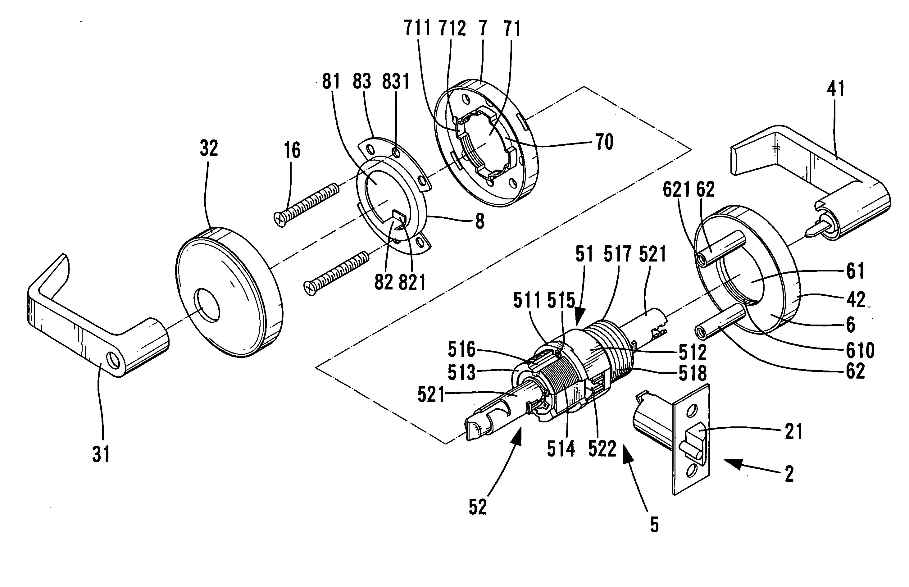
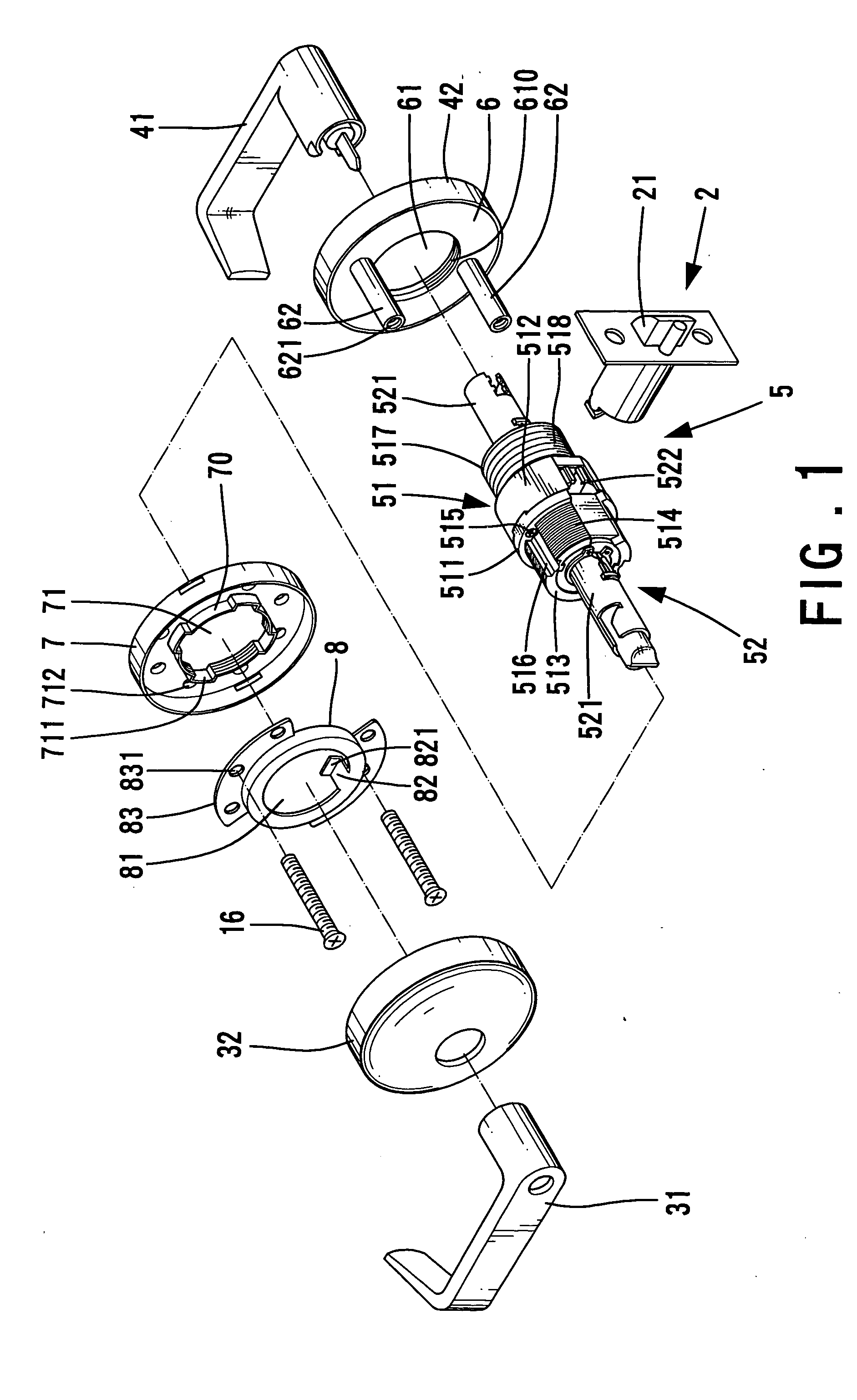
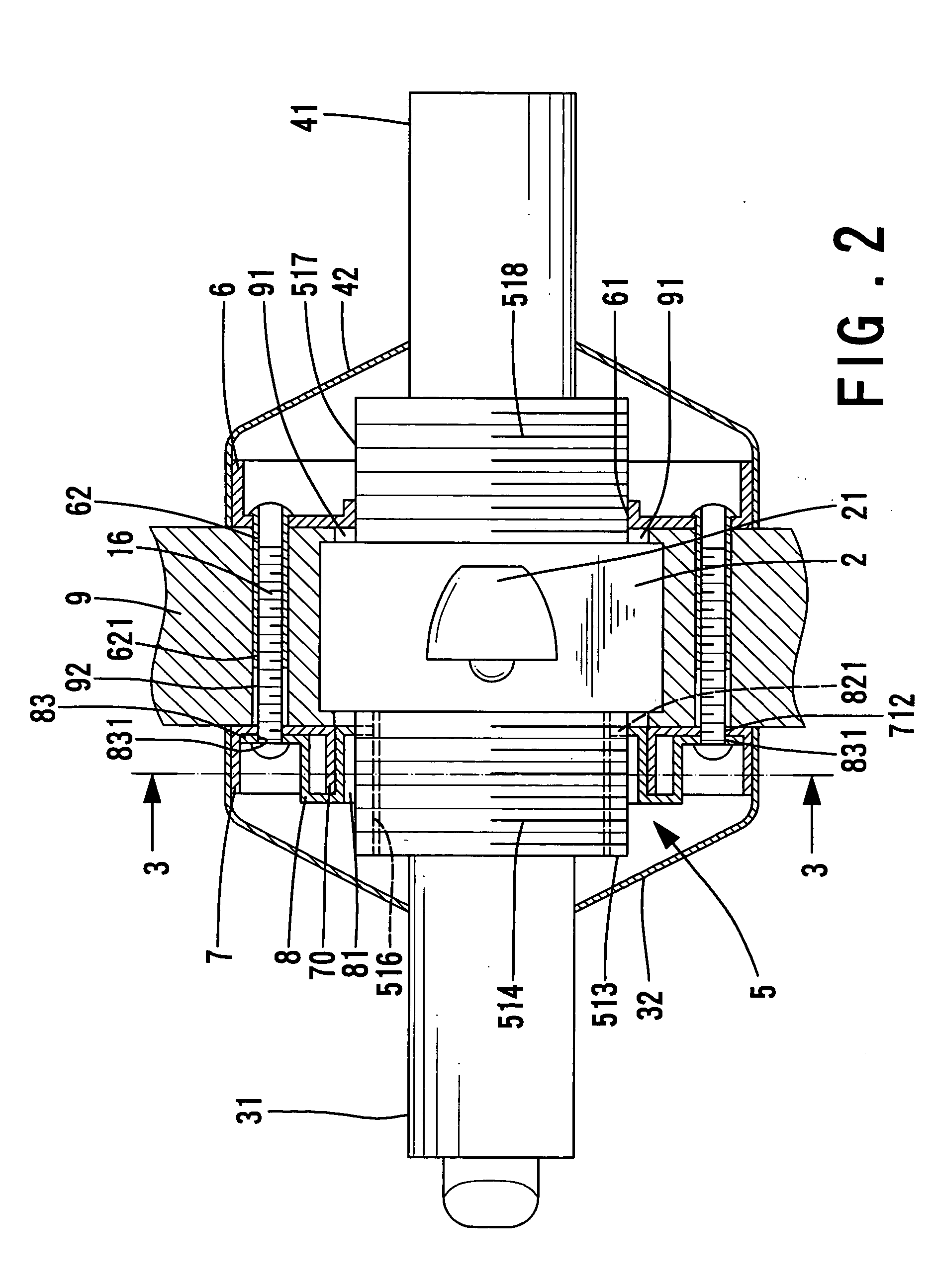
[0014] Referring to FIGS. 1 through 3, a lock in accordance with the present invention generally comprises a main body 5 to be mounted in a borehole 91 of a door 9. The lock further includes an inside rose 32, an outside rose 42, an inside handle 31, and an outside handle 41. The inside handle 31 and the outside handle 41 are of lever type, which is convenient to the disabled.

[0015] The main body 5 includes an inside seat 511 and an outside seat 512. The inside seat 511 includes a threaded section 513 having an outer threading 514. The outside seat 512 includes a threaded section 517 having an outer threading 518. A transmission assembly 52 is mounted inside the main body 5 and includes a spindle 521 and a retractor 522 operably connected to the spindle 521. Two ends of the spindle 521 are respectively connected to the inside handle 31 and the outside handle 41. Turning of either handle 31, 41 causes movement of the retractor 522, which, in turn, causes retraction of a latch bolt 2...


PUM


Abstract

A lock includes a main body having an outside seat and an inside seat around which an inside rose liner is mounted. A peripheral wall delimiting a central hole of the inside rose liner includes at least one pair of notches. A reinforcing ring is mounted round the inside seat and inside the inside rose liner. The reinforcing ring includes two tabs each having a distal end received in a respective groove of the inside seat, preventing relative rotation between the reinforcing ring and the main body. Two positioning posts extend from an outside rose liner mounted around the outside seat. Two fasteners extend through the reinforcing ring and the inside rose liner into screw holes of the positioning posts, thereby securing the reinforcing ring, the inside rose liner, and the outside rose liner together. The torque-resisting capacity is thus improved.

Description

BACKGROUND OF THE INVENTION [0001] 1. Field of the Invention [0002] The present invention relates to an inside rose liner for a lock. In particular, the present invention relates to a lock with improved torque-resistant capacity. [0003] 2. Description of the Related Art [0004] A typical door lock includes a main body having an inside seat and an outside seat, an inside rose liner securely mounted to the inside seat, an outside rose liner securely mounted to the outside seat, an inside rose, an outside rose, an inside handle, and an outside handle. The inside handle and the outside handle of lever type are convenient to the disabled. The inside seat includes two diametrically disposed grooves, and the inside rose liner includes two diametrically disposed protrusions respectively engaged in the grooves of the inside seat. Similar design is adopted in the outside seat and the outside rose liner. The door lock of such a structure is simple and has a low manufacture cost. Nevertheless, t...

Claims


Application Information

Patent Timeline
IPC IPC(8): E05B3/00E05B15/02E05B17/20E05B55/00E05B63/00E05B63/20
CPCE05B15/02E05B63/006E05B55/005E05B17/2084Y10T292/59Y10T292/91Y10T70/5832Y10T292/85Y10T292/57Y10T292/865Y10T292/564
Inventor SHEN, MU-LIN
Owner SHEN MU LIN
Why Eureka
Try Eureka