Air cleaner structure

Inactive Publication Date: 2005-05-12
HONDA MOTOR CO LTD
View PDF9 Cites 15 Cited by
  • Summary
  • Abstract
  • Description
  • Claims
  • Application Information

AI Technical Summary

Benefits of technology

[0010] Accordingly, it is an object of the present invention to provide an air cleaner structure which has flexibility in design and can achieve a smooth air-intake capability while keeping its function for separating rainwater or water contained in air.
[0015] Consequently, the air-intake duct can be downsized, so that flexibility in designing peripheral components is increased and, simultaneously, air containing little water can be delivered to the air cleaner.
[0016] In addition, the air cleaner in combination with the air-intake duct constitutes a structure that can supply cleaner air to the engine.
[0018] Owing to the vertically divided structure, the assembly for manufacture and disassembly can be easily performed. Also, the partitions are integrally formed respectively with the upper half and the lower half and are capable of being divided into the upper and lower portions.
[0021] With the provision of the plurality of partitions, the air-intake duct can generate an eddy current efficiently on the side of outlet port of the air-intake duct, and can separate water from the intake air.

Problems solved by technology

However, since the capacity of the surge tank 106 insignificantly large, there is a limit in the flexibility of designing the air cleaner.

Method used


Image

  • Air cleaner structure
  • Air cleaner structure
  • Air cleaner structure

Examples


Embodiment Construction

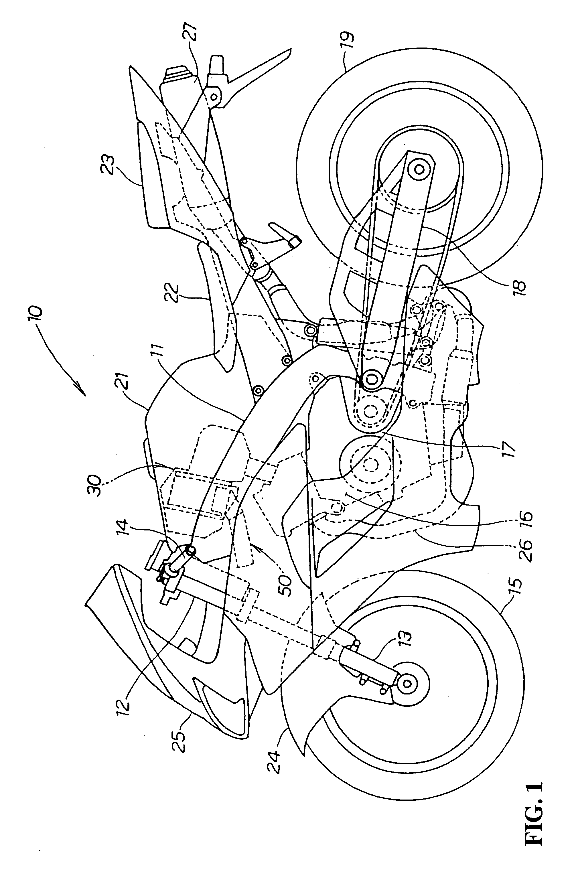
[0031] Referring now to the attached drawings, a best mode for carrying out the invention will be described. FIG. 1 is a side view of a two-wheel vehicle illustrating the structure of the air cleaner according to the present invention. A motorcycle 10 includes a main frame 11, front forks 13 and a handle 14 both attached to a steering shaft that is rotatably supported by a head pipe 12, which is provided at the front end of the main frame 11. A front wheel 15 is attached to the lower end of the front fork 13. An engine 16 attached below the main frame 11 with a speed changer 17 being provided integrally with the rear portion of the engine 16. A swing arm 18 is attached to the rear portion of the main frame 11 with a rear wheel 19 attached to the rear end of the swing arm 18. A fuel tank 21 is attached on the main frame 11 with a seat 22 attached behind the fuel tank 21. A fellow passenger's seat 23 is attached behind the seat 22.

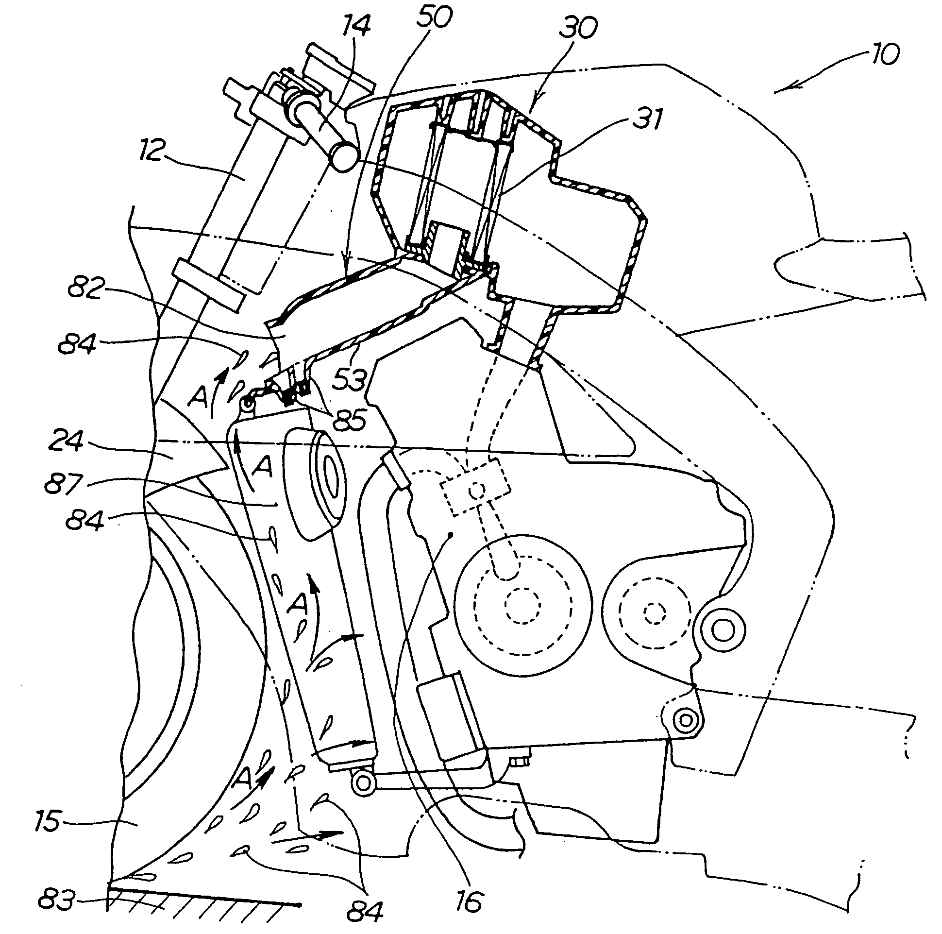
[0032] An air cleaner 30 is disposed behind the head ...


PUM


Abstract

An air cleaner structure that is capable of achieving smooth air-intake capability while separating water contained in air to supply clean air to the engine side. A lower half member of an air-intake duct is, when viewed from above, provided with a central partition and partitions located symmetrically in the vicinity of the central partition, partitions located near both ends, and narrowing passages and widening passages surrounded by the partitions. Air enters from the front of the vehicle body and flows like eddy currents from outlet ports of the widening passages to the outlet ports of the narrowing passages like eddy currents. Thus, coarse particulate and dust contained in the air stay on the outlet port side of the air-intake duct.

Description

BACKGROUND OF THE INVENTION CROSS-REFERENCE TO RELATED APPLICATIONS [0001] The present non-provisional application claims priority under 35 USC 119 to Japanese Patent Application No. 2003-376917 filed on Nov. 6, 2003 the entire contents thereof is hereby incorporated by reference. FIELD OF THE INVENTION [0002] The present invention relates to an air cleaner structure for a motorcycle. DESCRIPTION OF BACKGROUND ART [0003] An air cleaner for a motorcycle is a device having a function for reducing or removing water taken into the air cleaner when it rains, or for reducing an air-intake sound of an engine. [0004] Therefore, an important performance of the air cleaner is how water contained in the intake air can be removed by an element constituting the air cleaner or in an air-intake duct, which is a passage for introducing outside air. [0005] An air cleaner of a type which accumulates water contained in intake air or rainwater in a surge tank that is provided in an intake duct and disc...

Claims


Application Information

Patent Timeline
IPC IPC(8): B62J99/00F02M35/024F02M35/08F02M35/10F02M35/16
CPCF02M35/02F02M35/10013Y02T10/146F02M35/162F02M35/168F02M35/10262Y02T10/12Y02A50/2351
Inventor NAKAGOME, HIROSHIKONISHI, KATSUYUKIHAMADA, AKIHIROINADA, KAORI
Owner HONDA MOTOR CO LTD
Why Eureka
Try Eureka