Light-emitting unit and method of producing the same

Inactive Publication Date: 2007-05-24
TPO HONG KONG HLDG
View PDF8 Cites 17 Cited by
  • Summary
  • Abstract
  • Description
  • Claims
  • Application Information

AI Technical Summary

Benefits of technology

[0009] The solid state light source, for example a light emitting diode (LED), a LED die, a chip from an LED, a laser, a laser diode, etc., is mounted on the leadframe. Mounting the solid state light source on the leadframe provides a firm and secure fixation of the solid state light source as well as a firm and secure support to this part of the lightguide. An advantage of the present mounting is that the leadframe provides better mechanical stability and firm support as compared to lead pins or lead films that tend to easily bend and break. Another advantage of the leadframe is the improved mechanical stability it provides to the solid state light source and to the part of the lightguide around the vicinity of the leadframe.
[0031] In a further embodiment, the method of producing the light-emitting unit comprises two molding steps instead of a single molding step. In the molding step described above, the molding material is made of a heat and / or UV resistant material forming a first part of the lightguide. This first molding step is followed by a further molding step wherein the first part of the lightguide is then molded with a material possessing higher optical transmittance than the heat and / or UV resistant material forming a second part of the lightguide. The advantages have been discussed earlier. A further advantage is that after forming the first part of the lightguide in the first molding step it becomes easier to transport the light-emitting unit to another production unit and perform the second molding step. A further advantage is the modularity in the production of different products based on similar designs, for example after forming the fist part of the lightguide, the second part of the light guide can be formed in different dimensions.

Problems solved by technology

The above-mentioned light-emitting unit has several components, which are difficult to assemble during production, as the components are vulnerable and therefore complex to handle during production.
Moreover, the light-emitting unit thus obtained is a fragile device in itself and has to be handled with care for further processing as for example in assembling a backlight unit.

Method used


Image

  • Light-emitting unit and method of producing the same
  • Light-emitting unit and method of producing the same
  • Light-emitting unit and method of producing the same

Examples


Embodiment Construction

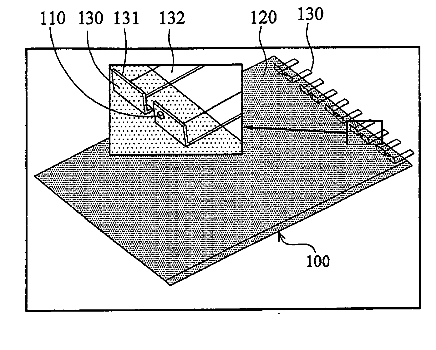
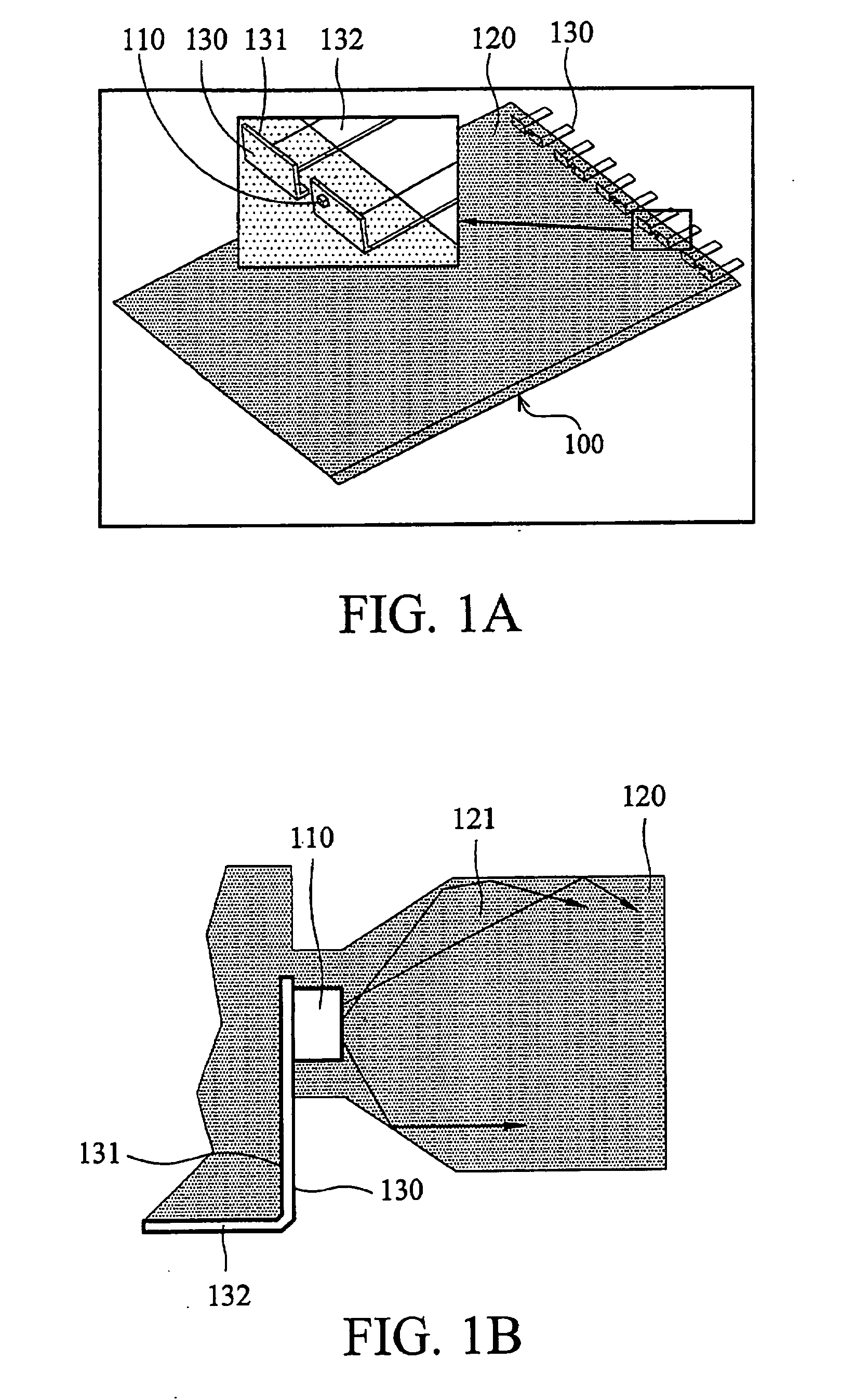
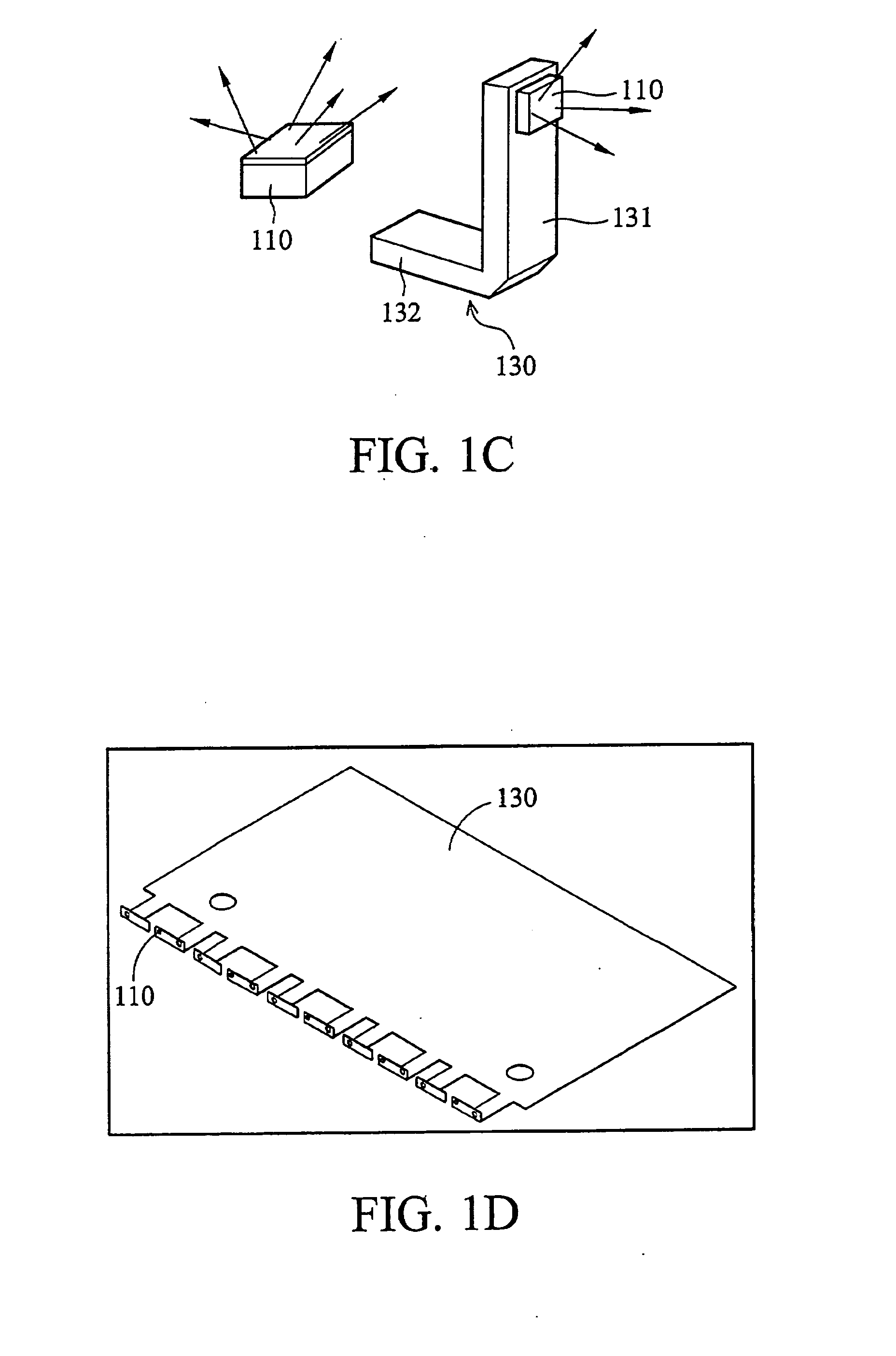
[0049]FIG. 1A shows a schematic representation of a light-emitting unit 100 according to the invention comprising an array of solid state light sources 110 mounted on a leadframe 130 and molded with a molding material, which forms at least a part of the lightguide 120. The inset in FIG. 1A shows an individual element from the array of the solid state light sources 110, wherein the solid state light source 110, the leadframe 130 and the molding material forming at least a part of the lightguide 120 are clearly indicated.

[0050] Typically light emitting diodes (LED), LED dies, chips from an LED, lasers, laser diodes, and the likes are used as solid state light sources 110. The light-emitting unit 100 may comprise packaged or unpackaged solid state light sources 110. The solid state light source 110 may be a monochromatic source, an RGB source or a white light source.

[0051] The leadframe 130 comprises a first part 131 and a second part 132, the first part 131 arranged at 90 degrees to...


PUM


Abstract

A light-emitting unit comprising a solid state light source mounted on a leadframe and a lightguide into which the solid state light source is to in-couple light into its light guiding direction. The solid state light source and at least a part of the leadframe are molded with a molded material, wherein the molding material forms at least a part of the lightguide.

Description

BACKGROUND OF THE INVENTION [0001] 1. Field of the Invention [0002] This invention relates to a light-emitting unit. [0003] 2. Description of the Related Art [0004] An embodiment of a light-emitting unit as described above is known from EP-0751340-A2. This document discloses a light-emitting unit including one or more light sources, which emit light into a lightguide. The lightguide is for example a flat rectangular plate having a lateral direction and a longitudinal direction. The lateral direction is along the breadth of the plate and the longitudinal direction is along the length of the plate. The light guiding direction is typically chosen as the longitudinal direction. The light sources are placed along a side in the lateral direction, for example in cavities, slots or openings, and connected to the lightguide mechanically by means of bonding, potting, gluing or molding. The arrangement is such that the light emitted from the light sources is input into the lightguide along the...

Claims


Application Information

Patent Timeline
IPC IPC(8): G02B6/43
CPCG02B6/0021G02B6/0028G02B6/0068G02B6/0073G02B6/0083
Inventor VERWEG, FRANZWEL, PIETER VAN DERVAN MONTFORT, V.J.J.DE BOER, HEDZERANSEMS, WILL
Owner TPO HONG KONG HLDG
Why Eureka
Try Eureka