Frequency divider system
a frequency divider and frequency division technology, applied in the field of frequency division techniques, can solve the problems of inability to include separate crystal oscillators in the electronic device, inability to synchronize, and only operate the components of the electronic devi
- Summary
- Abstract
- Description
- Claims
- Application Information
AI Technical Summary
Benefits of technology
Problems solved by technology
Method used
Image
Examples
Embodiment Construction
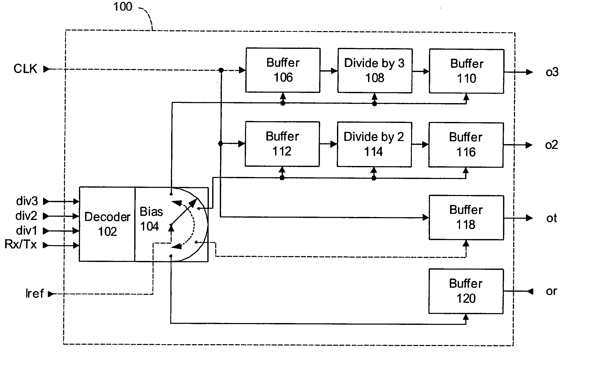
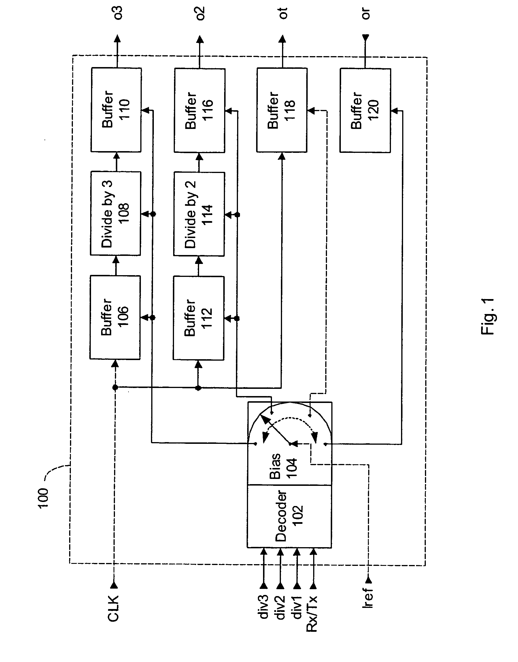
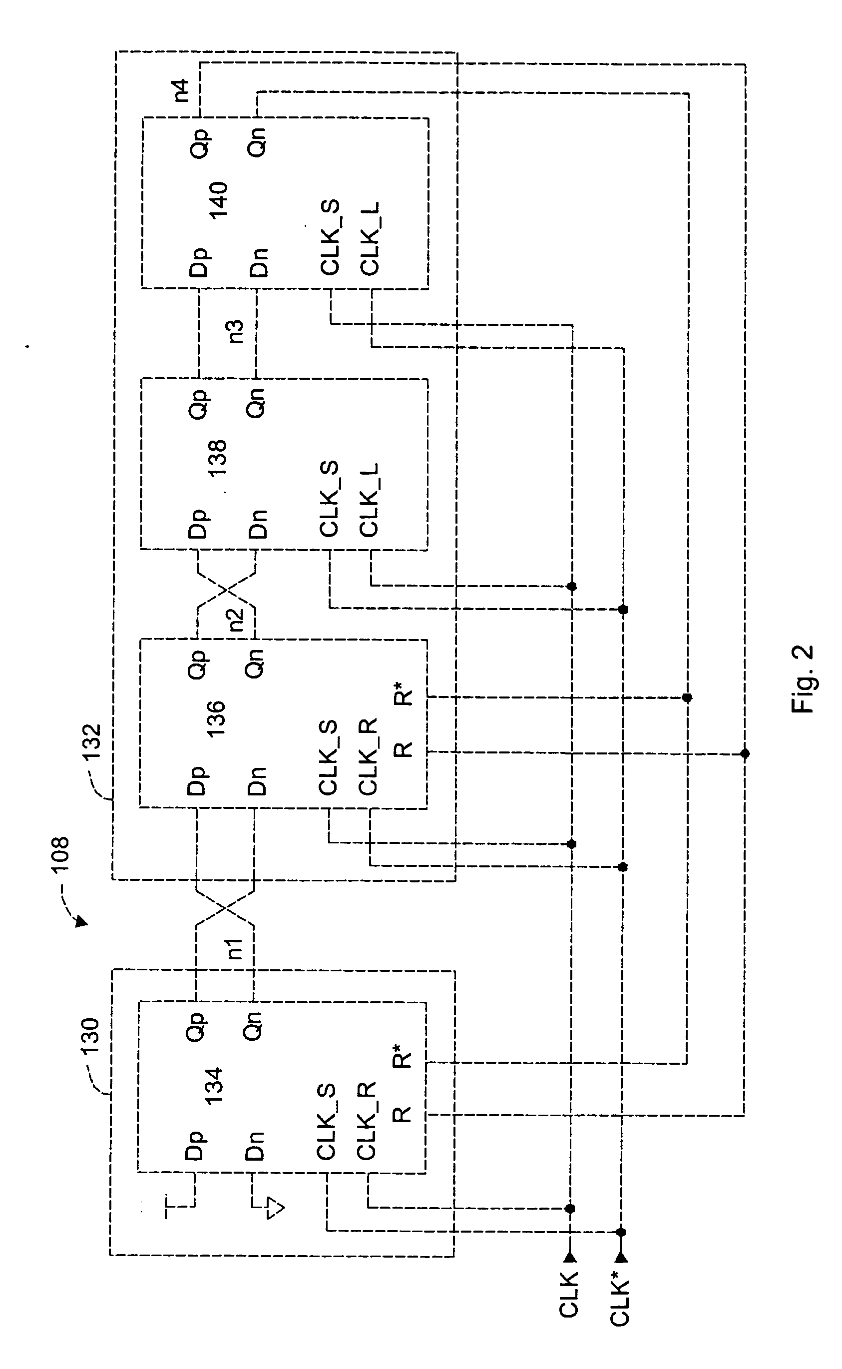
[0020] A frequency divider circuit for providing a divided clock signal having a frequency that is a factor less than the frequency of an incoming system clock signal is disclosed. The frequency divider includes a clock generator circuit coupled to a delay circuit that operates in an active and a reset phase to provide a divided clock signal from the system clock signal. In the active phase, the clock generator circuit drives the divided clock signal to a first logic state until a reset signal is received. The delay circuit then generates the reset signal at a number of system clock transitions after the divided clock signal is driven to the first logic state. In the reset phase, the first two flip flops are reset only, the delay formed by the second two flip-flops does not have any reset inputs, however, their inputs are reset to a logic ‘0’ two clock cycles after the reset signal is asserted. The delay circuit therefore maintains a 50% duty cycle for the divided clock signal. More...
PUM
 Abstract
Description
Claims
Application Information
 - R&D
- Intellectual Property
- Life Sciences
- Materials
- Tech Scout
- Unparalleled Data Quality
- Higher Quality Content
- 60% Fewer Hallucinations
Browse by: Latest US Patents, China's latest patents, Technical Efficacy Thesaurus, Application Domain, Technology Topic, Popular Technical Reports.
© 2025 PatSnap. All rights reserved.Legal|Privacy policy|Modern Slavery Act Transparency Statement|Sitemap|About US| Contact US: help@patsnap.com


