System and method for radar detection and calibration

a radar detection and calibration technology, applied in the field of radar detection and calibration, can solve the problems of less time available to deploy defense systems or even gaps in detection coverage of radar systems, and the cost of manned test aircraft for this purpose, and achieve the effect of reducing the cost of manned test aircraft and reducing the cost of manned testing

Inactive Publication Date: 2005-06-16
THE BOEING CO
View PDF31 Cites 35 Cited by
  • Summary
  • Abstract
  • Description
  • Claims
  • Application Information

AI Technical Summary

Benefits of technology

[0004] The present invention solves these problems, providing a system and method for radar detection and calibration that accounts for existing atmospheric conditions and radar condition without the need to use manned aircraft. Generally, in accordance with one aspect of the present invention a relatively small and inexpensive UAV is used to provide such detection and calibration, which may also include signal augmentation to simulate the radar cross-section of larger targets.

Problems solved by technology

The performance of a radar system can be affected by atmospheric conditions, thereby providing erroneous information that can result in undesirable and even severe consequences.
Using a military application as an example, a radar used to detect enemy aircraft may, because of existing atmospheric conditions and radar condition, actually see a target at significantly less than the expected range, resulting in less time being available to deploy defense systems or even gaps in detection coverage of a system of radars.
However, the use of manned test aircraft for this purpose is expensive and poses a safety risk to the pilot.
Moreover, because they must be of a sufficient size to be manned, they are limited in their use as radar detection and calibration targets where small radar cross-sections are desired or required.

Method used


Image

  • System and method for radar detection and calibration
  • System and method for radar detection and calibration
  • System and method for radar detection and calibration

Examples


Embodiment Construction

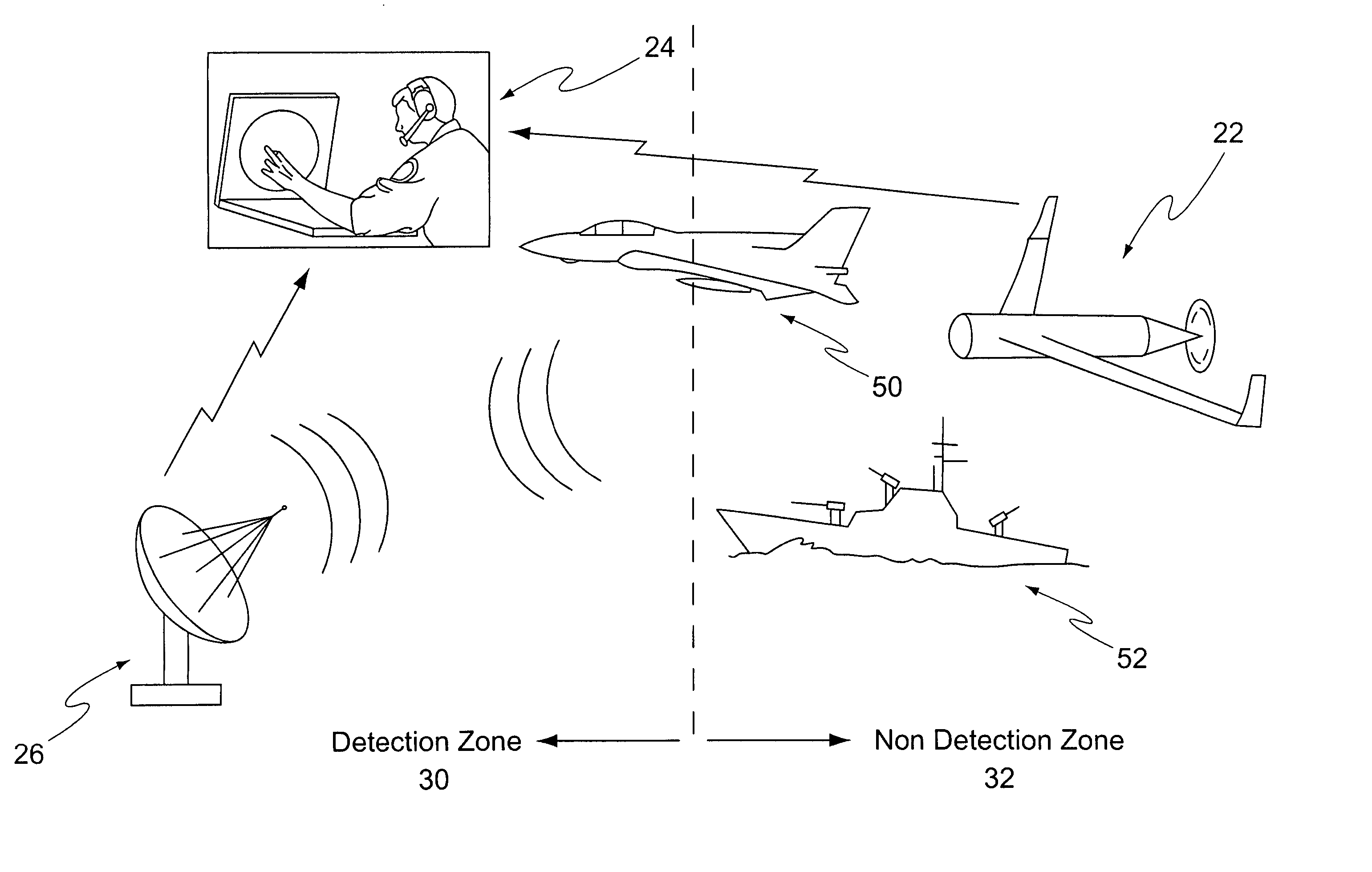
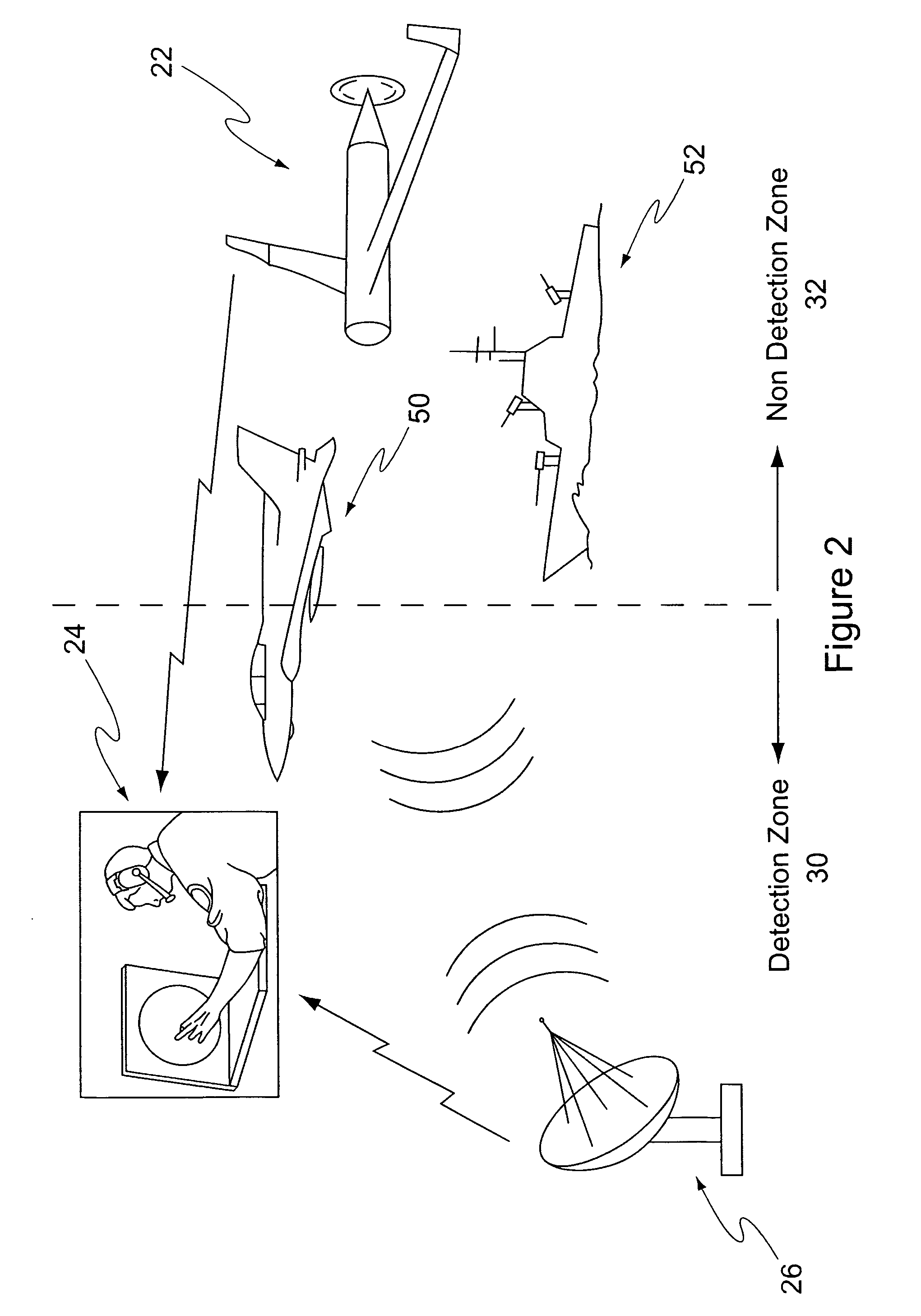
[0011] Referring to the drawings, there is shown a preferred embodiment of a radar detection and calibration system 20 of the invention generally comprising a calibration target 22 and a calibration device 24 for calibrating a radar system 26. The radar system 26 has a detection zone 30 for a particular target within which the radar system is able to detect the target. The size of the detection zone 30 is dependent upon the size of the target's radar cross-section, such that the greater the target's radar cross-section the greater the radar's detection zone for that target. The radar's non-detection zone is identified as the zone 32 extending beyond the detection zone.

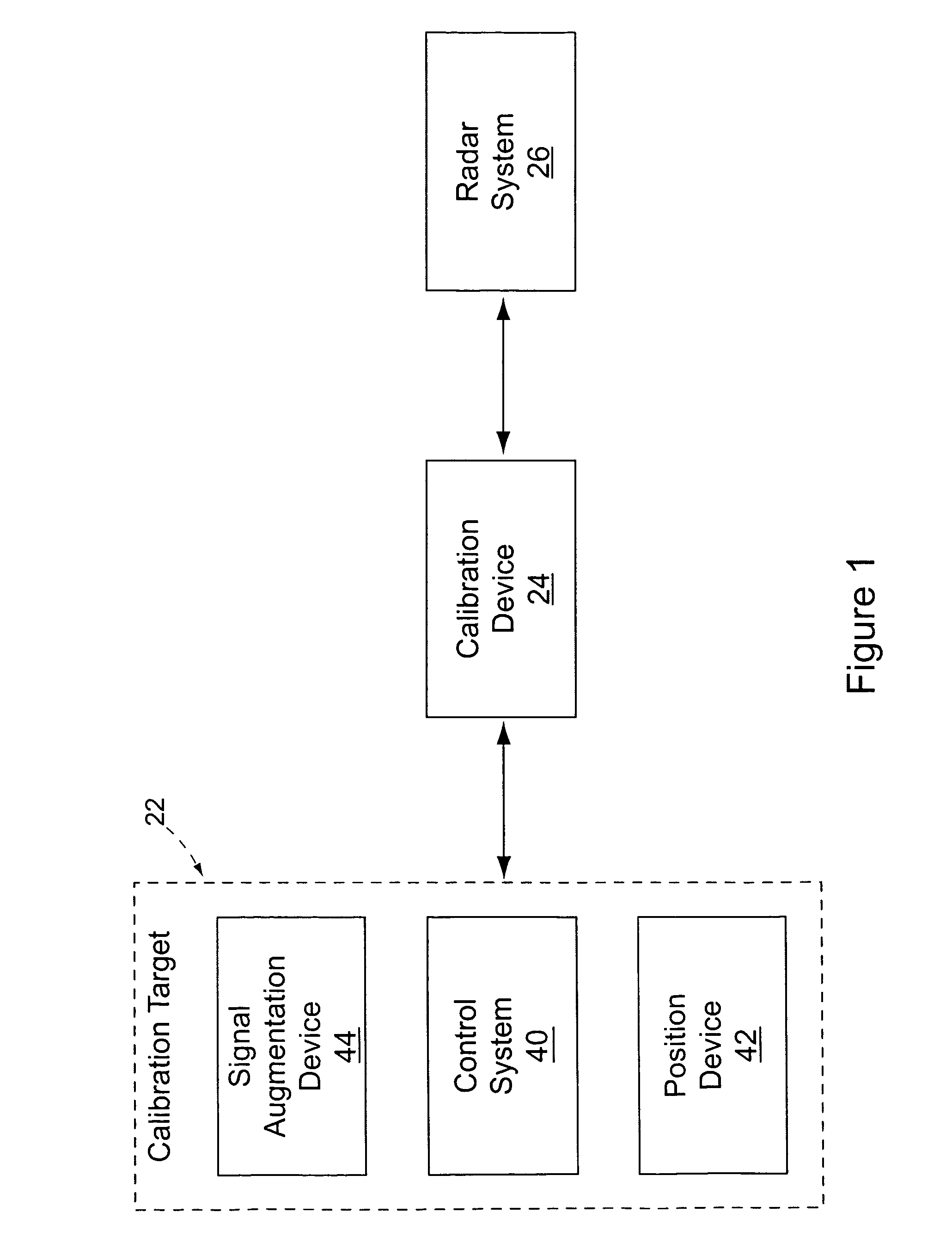
[0012] The calibration target 22 is preferably a UAV, such as the BOEING SCAN EAGLE™, although any suitable UAV may be used. The UAV includes a control system 40 adapted to navigate the UAV, and a position device 42 adapted to provide an actual position of the UAV at any given time.

[0013] In accordance with a preferr...


PUM


Abstract

A system and method for radar detection and calibration. By measuring the true range of a calibration target on entry to the radar's detection zone, the actual detection capability of the radar in current atmospheric conditions with the actual radar can be determined. The radar system is also adapted to determine a sensed position at a sensed time of a target in the radar's detection zone. A calibration target, preferably an unmanned air vehicle (UAV), includes a position device for determining the actual position of the calibration target. A calibration device communicates with the radar system and the calibration target and receives the sensed and actual positions of the calibration target. The calibration device calculates the error between the sensed position and the actual position and adjusts the radar system to minimize the error. The target may include a signal augmentation device to augment the radar cross-section of the target to replicate the radar cross-sections of targets of various types. In this manner the true detection range of the radar system can be determined for various types of targets under existing atmospheric conditions.

Description

FIELD OF THE INVENTION [0001] The present invention generally relates to a system and method for radar detection and calibration, and more particularly a radar detection and calibration system and method utilizing an unmanned air vehicle (UAV) as a calibration target. BACKGROUND OF THE INVENTION [0002] The performance of a radar system can be affected by atmospheric conditions, thereby providing erroneous information that can result in undesirable and even severe consequences. Atmospheric conditions and radar mechanical and electrical conditions can significantly reduce the radar's detection range such that the detection range is expected to be much greater than its true range given existing atmospheric conditions and radar condition. By way of example, a radar normally having a detection range of 100 miles may under particular atmospheric conditions have an actual range of 90 miles. Using a military application as an example, a radar used to detect enemy aircraft may, because of ex...

Claims


Application Information

Patent Timeline
Patent Type & Authority Applications(United States)
IPC IPC(8): G01S7/40
CPCG01S7/4004
Inventor WITTENBERG, PETER S.HAYN, JOHN
Owner THE BOEING CO
Why Eureka
Try Eureka