Probabilistic model for a positioning technique

a probability model and positioning technology, applied in direction finders using radio waves, instruments, wireless communication, etc., can solve the problems of difficult automatic processing, large number of sample points obtained by physical calibration, and inability to predict signal values between two locations

Inactive Publication Date: 2005-06-16
AIRISTA FLOW INC +1
View PDF16 Cites 85 Cited by
  • Summary
  • Abstract
  • Description
  • Claims
  • Application Information

AI Technical Summary

Benefits of technology

[0021] The location-estimating step can be performed in the target device. In this case, the target device must comprise the probabilistic model and carry out the location-estimating software routines. An advantage gained by performing the location-estimating step in the target device is that the target device does not have to transmit the signal value observations to have its location estimated.
[0022] Alterna

Problems solved by technology

A problem is that obtaining a large number of sample points by physical calibration is time-consuming and expensive.
This process is difficult to perform automatically.
But such a combined probabili

Method used


Image

  • Probabilistic model for a positioning technique
  • Probabilistic model for a positioning technique
  • Probabilistic model for a positioning technique

Examples


Embodiment Construction

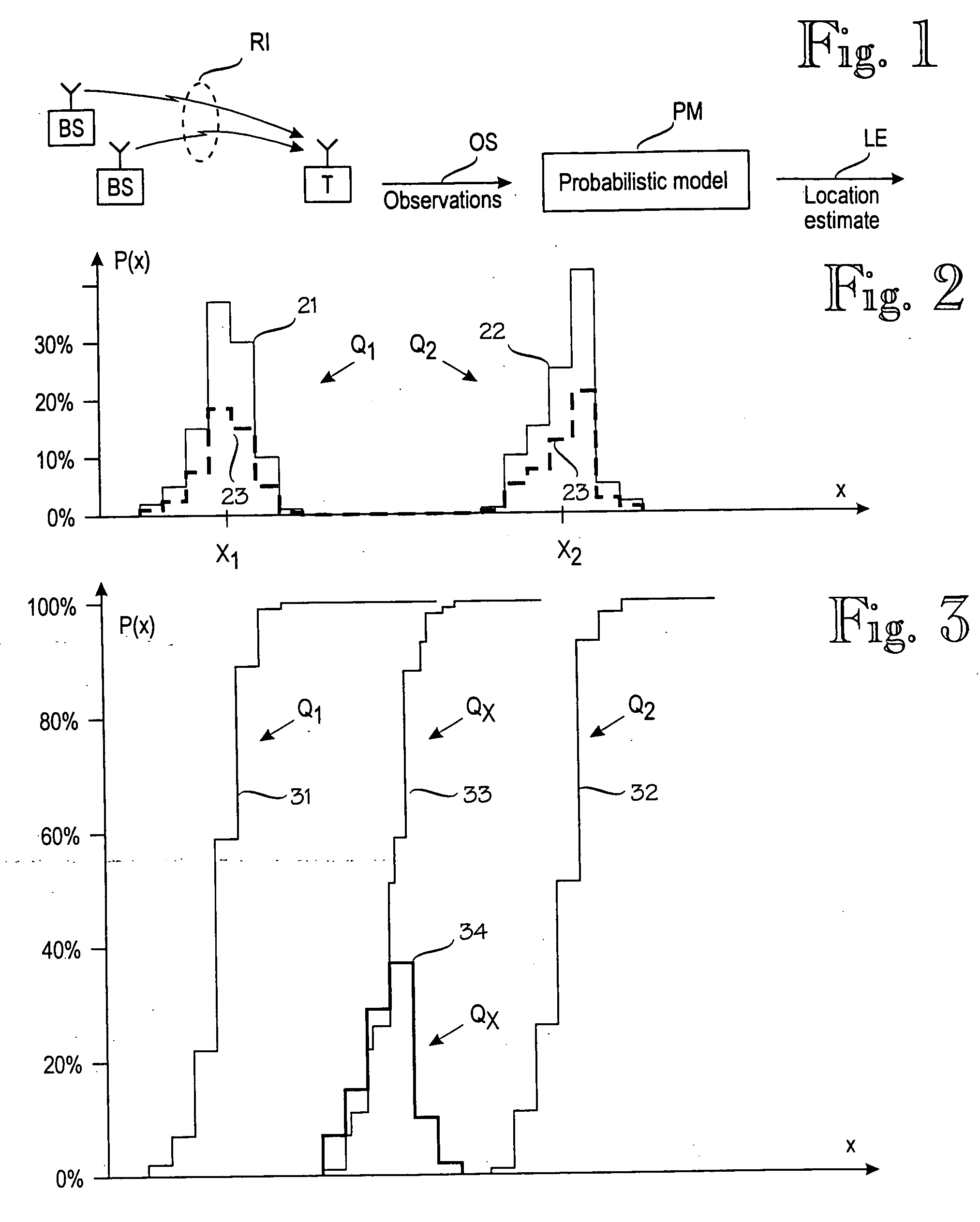
[0034]FIG. 3 illustrates the principle of the invention. The invention is based on the idea of combining the inverse cumulative distribution functions of expected signal values at various locations, instead of combining the signal values or their probability distributions. FIG. 3 is drawn to the same scale as FIG. 2, and the x-axis are aligned. Curve 31 represents the cumulative distribution function for location Q1. For each nonzero probability value in probability distribution 21, there is a corresponding step in the cumulative distribution function 31. Similarly, curve 32 represents the cumulative distribution function for location Q2. Curve 33 is a cumulative distribution function for a location QX (such as a new sample point) between locations Q1 and Q2. In this example, the new sample point QX is assumed to be in the middle of a straight line from Q1 to Q2, and the cumulative distribution function 33 is created by the following algorithm: for each of several dependent variable...


PUM


Abstract

A model construction module (MCM) for constructing a probabilistic model (PM) of a wireless environment (RN) in which a target device (T) communicates using signals that have a measurable signal value (x), such as signal strength. The model construction module forms several submodels (611-631) of the wireless environment (RN). Each submodel indicates a probability distribution (F1-F3) for signal values at one or more locations (Q1-QY) in the wireless environment. The module combines the submodels to a probabilistic model (PM) of the wireless environment (RN), such that the probabilistic model indicates a probability distribution for signal values at several locations in the wireless environment. Alternatively, the model may insert new locations to a single model based on a combination of existing locations. The combination of submodels or existing locations comprises combining the inverse cumulative distribution functions of the submodels or existing locations.

Description

[0001] This is a continuation of International Application No. PCT / FI03 / 00413, filed May 27, 2003, which claims priority from Finnish Application No. 20021044, filed May 31, 2002, the contents of both of which are incorporated herein by reference. BACKGROUND OF THE INVENTION [0002] The invention relates generally to a positioning technique in which a target device's location is estimated on the basis of observations on the target device's wireless communication environment. FIG. 1 schematically illustrates an example of such a positioning technique. A target device T communicates via base stations BS via a radio interface RI. In this example, the communication is assumed to be radio communication. The target device T observes signal values at the radio interface RI. The observation set OS is applied to a probabilistic model PM that models the target device's wireless communication environment and produces a location estimate LE. [0003] A practical example of the target device is a d...

Claims


Application Information

Patent Timeline
IPC IPC(8): G01S3/06G01S5/02H04W64/00
CPCG01S3/06H04W64/00G01S5/0252G01S5/02528
Inventor MISIKANGAS, PAULIMYLLYMAKI, PETRI
Owner AIRISTA FLOW INC
Why Eureka
Try Eureka