Binoculars with an integrated laser rangefinder

a laser rangefinder and binocular technology, applied in the field of binoculars with an integrated laser rangefinder, can solve the problems of awkward focusing of eyepieces, cumbersome binocular housing, and heavy weigh

Active Publication Date: 2005-06-16
LEICA GEOSYSTEMS AG +1
View PDF10 Cites 32 Cited by
  • Summary
  • Abstract
  • Description
  • Claims
  • Application Information

AI Technical Summary

Benefits of technology

[0013] The cylindrical sleeve part accommodates the laser transmitter, whose optical axis is therefore located physically close to the optical axis of the objective picking up the reflected measuring beams. The sleeve part is firmly

Problems solved by technology

The binocular housing is relatively cumbersome and heavy.
Focusing the eyepieces is awkward, so that these devices are normally use

Method used


Image

  • Binoculars with an integrated laser rangefinder
  • Binoculars with an integrated laser rangefinder
  • Binoculars with an integrated laser rangefinder

Examples


Embodiment Construction

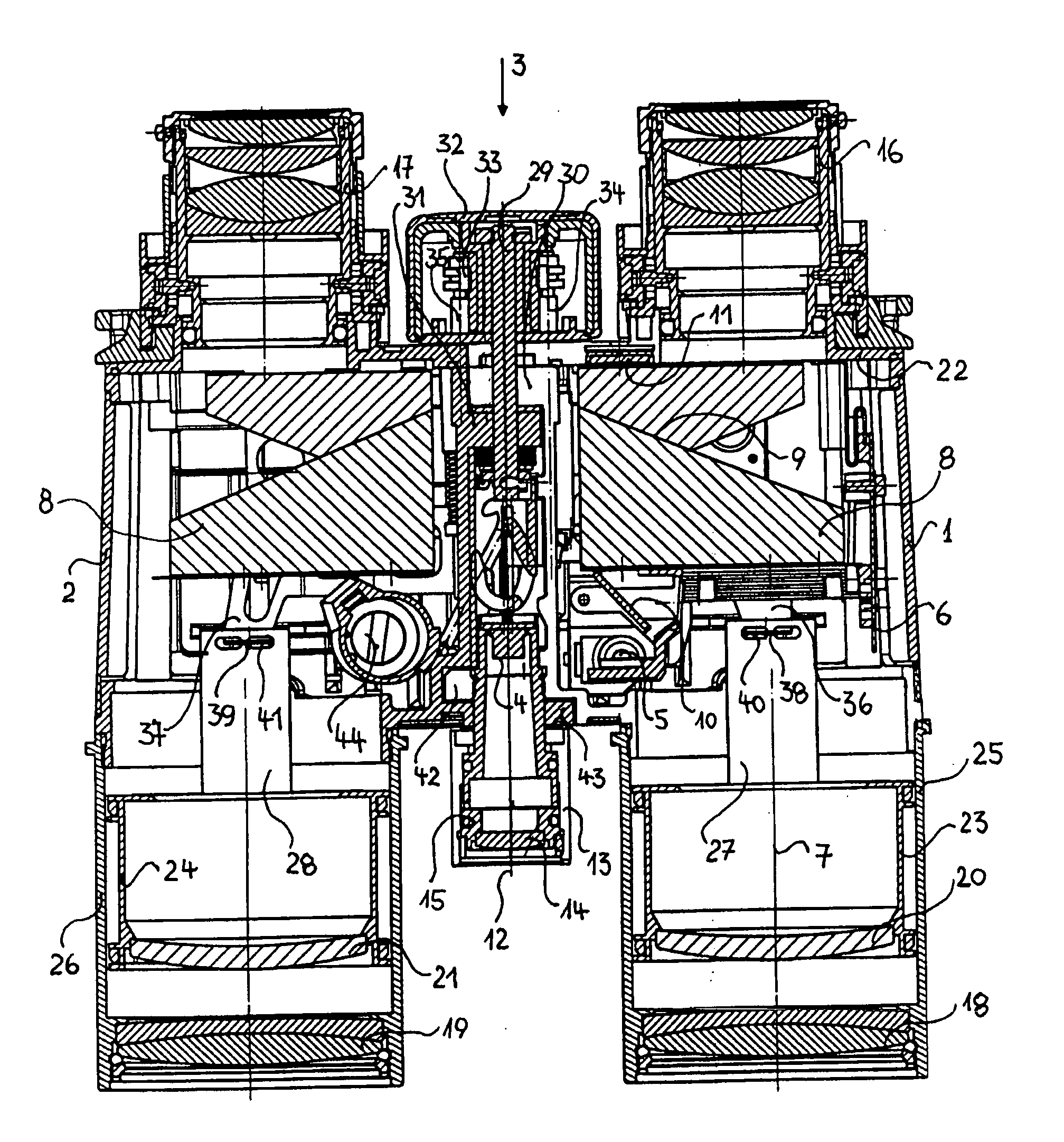
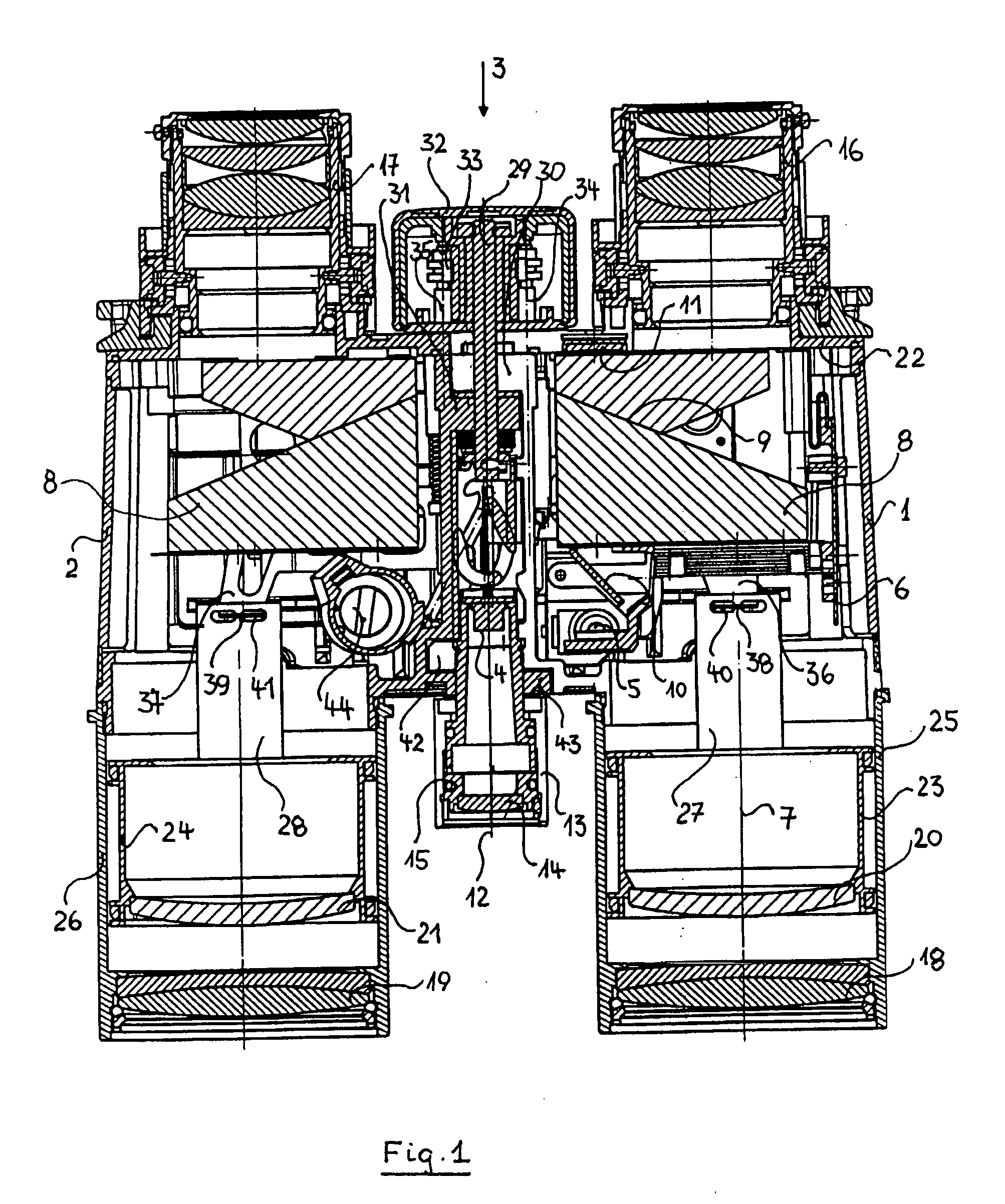
[0018] The sectional illustration according to FIG. 1 shows a view of the underside of the binoculars. A first housing part 1 and a second housing part 2 are connected to each other via a jointed bridge 3 for the purpose of eye width adjustment.

[0019] Firmly connected to the first housing part 1 are a transmitter 4, a receiver 5 and a display element 6, as optoelectronic elements of a laser rangefinder. The optical axis of the receiver beam path for the rangefinding coincides with the optical observation axis 7 in the first housing part 1.

[0020] The receiving beam path for the rangefinding is coupled out at the deflection and imaging inversion prism 8, corresponding to one of the beam paths described in DE 199 33 172 C1. The infrared measuring beam reflected at the beam-splitting cemented surface 9 of the prism system 8 is led on to the receiver 5 through a beam-splitting mirror 10 following further deflection. The beam of the measuring result, displayed visibly on the display ele...


PUM


Abstract

Binoculars having an integrated laser rangefinder has two separate housing parts ( 1, 2 ) with eyepieces ( 16, 17 ) and objectives ( 18, 19 ), which are connected to each other via a jointed bridge ( 3 ) for eye width adjustment, and in which the first housing part ( 1 ) contains a transmitter ( 4 ) and a receiver ( 5 ) of the laser rangefinder and also an optoelectronic display element ( 6 ) in a fixed arrangement with respect to an optical observation axis ( 7 ).

Description

CROSS-REFERENCE TO RELATED PATENT APPLICATIONS [0001] The right of foreign priority is claimed based upon Federal Republic of Germany Priority Application 103 58 669.5, filed Dec. 12, 2003, and Federal Republic of Germany Priority Application 10 2004 054 182.5, filed Nov. 10, 2004, the entire disclosures of which, including the specifications, drawings, claims and abstracts, are incorporated herein by reference. BACKGROUND OF THE INVENTION [0002] The invention relates to binoculars with an integrated laser rangefinder. [0003] In binoculars of this type disclosed by DE 37 04 848 C2, the two observation systems comprising objective, image inversion system and eyepiece are arranged in a common housing. In order to adjust the eye width, it is only possible for the eyepieces to be adjusted with respect to each other. In the process, the position of the optical axis of the eyepieces with respect to the optical axis of the objectives and inversion systems change. Focusing is generally carr...

Claims


Application Information

Patent Timeline
IPC IPC(8): G01C3/00G01C3/04G02B23/18
CPCG01C3/04
Inventor PERGER, ANDREASKETTLER, GERNOT
Owner LEICA GEOSYSTEMS AG
Why Eureka
Try Eureka