
Electronic instrument

a technology of piezoelectric and sounding bodies, applied in the field of piezoelectric sounding bodies, can solve the problems of difficult to produce flat frequency characteristics, easy irregularity of the piezoelectric electronic part,

Inactive Publication Date: 2005-06-16
TAIYO YUDEN KK
View PDF10 Cites 31 Cited by
  • Summary
  • Abstract
  • Description
  • Claims
  • Application Information

AI Technical Summary

Problems solved by technology

In addition, the acoustically transducing electronic part of the piezoelectric type easily becomes irregular in frequency characteristics due to resonance phenomena, and is difficult to produce flat frequency characteristics.

Method used


Image

  • Electronic instrument
  • Electronic instrument
  • Electronic instrument

Examples


embodiment 1

(1) Embodiment 1

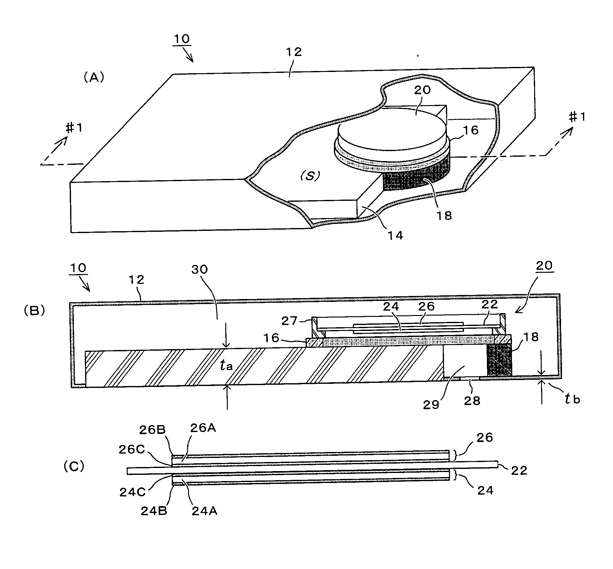
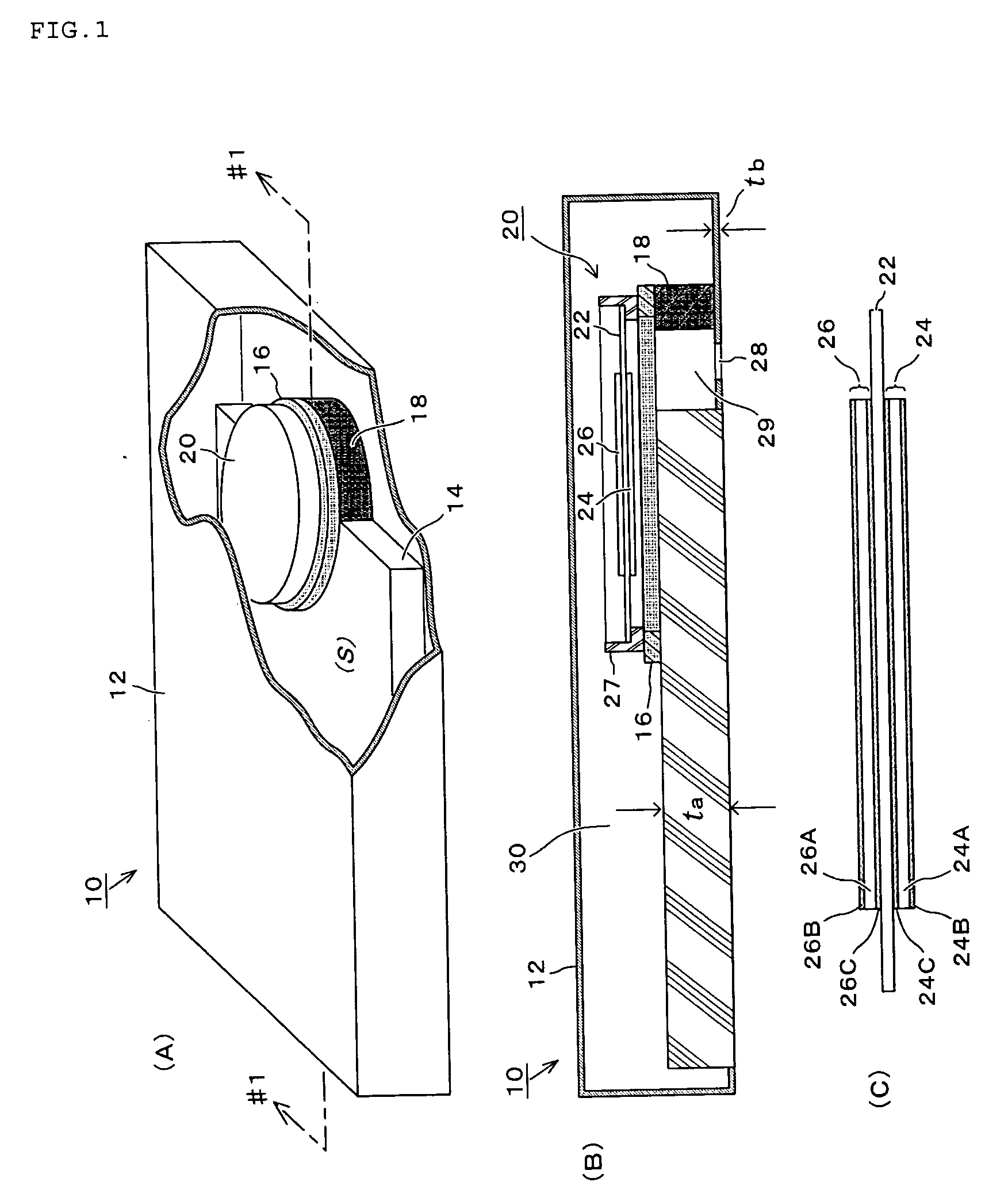
[0021] At first, referring to FIGS. 1 to 7, the embodiment 1 of the invention will be explained. FIG. 1A shows the whole structure of the embodiment 1, and a cross section seen in a direction of arrows along #1-#1 of FIG. 1A is shown in FIG. 1B. Enlarged vibrating parts of FIG. 1B are shown in FIG. 1C.

[0022] In these views, as to the electronic instrument 10, various electronic parts are housed in the casing 12, and a mass part (mass body) 14 among the parts is shown. The mass part 14 may, for example, comprise such parts having comparatively large mass, for example, a liquid crystal display of the portable telephone or a battery box holding a charging battery. It may be an assembly of several parts. The piezoelectric sounding body 20 is mounted at a back side of the mass part 14 (the inside of the casing 12 of the mass part 14) via a ring shaped cushioning material or a spacer 16. Specifically, the piezoelectric sounding body 20 may be closely adhered to the mass p...

embodiment 2

(2) Embodiment 2

[0042] In reference to FIG. 8, the embodiment 2 of the invention will be explained. The electronic instrument 50 of this embodiment is similar to the embodiment 1 in that the piezoelectric sounding body 20 is positioned on the back of the mass part 14 and mounted, but different in that the sound issuing hole 58 is formed on the front and back sides of the casing 12. In this embodiment, at the backside of the piezoelectric sounding body 20, a curved partition 52 is provided between the piezoelectric sounding body 20 and the casing 12, and the interior space of this partition 52 continues to the surface of the piezoelectric sounding body 20. Further, at the other end of the piezoelectric sounding body, a sub air-chamber 54 is defined, and the sub air-chamber 54 and the main air-chamber 56 are divided by the partition 52. The main air-chamber 56 communicates with the front and back sides of the casing 12, each provided with the respective sound issuing holes 58.

[0043] ...

embodiment 3

(3) Embodiment 3

[0044] In reference to FIGS. 9 and 10, an embodiment 3 of the invention will be explained. The embodiment shown in FIG. 9A is in some ways similar to the above mentioned embodiment 1, comprising the piezoelectric sounding body 20, the cushioning material 16 and partition 18. The example shown in FIG. 9B unifies the partition 18A and the mass part 14 as one body. The example shown in FIG. 9C unifies the cushioning material and the partition 18B as one body. FIG. 9D installs the piezoelectric sounding bodies 20L, 20R at left and right ends of the mass part 14 respectively via the cushioning materials 16L, 16R and the partitions 18L, 18R, for example, so as to reproduce the sounds of 2 channels such as a stereo. The example shown in FIG. 9E installs the piezoelectric sounding body 20 at the corner of the mass part 14 via the cushioning material 16 and the partition 18C. The example shown in FIG. 9F provides in advance a cutout 14B for the piezoelectric sounding body in ...


PUM


Abstract

It is designed to restrain vibration of a casing, efficiently drive a piezoelectric sounding body (such as a piezoelectric speaker) and flatten sound pressure characteristic within the electronic instrument requiring the miniaturized type, light weight, and thin type in the electronic instrument, in particular the portable telephone. For accomplishing these objects, at a back side of a mass part within the casing of the electronic instrument, the piezoelectric sounding body is mounted via a ring shaped cushioning material. At a part not overlapping with the mass part, a partition is provided. A main air-chamber is tightly formed by the mass part, the piezoelectric sounding body, and the partition, and in the casing within the main air-chamber, a sound issuing hole is formed. The sound outputted from the upper face into the main air-chamber is outputted outside of the casing from the sound issuing hole. Vibration generated from the piezoelectric sounding body interferes with the mass part, so that transmission of vibration to the casing is restrained, and since the space of the inside and outside of the piezoelectric sounding body is served as the air-chamber, the sound pressure characteristic is made flat.

Description

FIELD OF THE INVENTION [0001] The present invention relates to piezoelectric sounding bodies (such as piezoelectric type speakers) functioning as acoustically transducing electronic parts of buzzers or speakers, and relates to an improvement of electronic instruments such as portable telephones utilizing such piezoelectric speakers. BACKGROUND OF THE INVENTION [0002] Acoustically transducing electronic parts used in portable telephones include a dynamic type making use of electromagnetic induction, and a piezoelectric type making use of piezoelectric phenomena. In the acoustically transducing electronic part of the dynamic type, as one embodiment shown in FIG. 11A, a circular diaphragm 900 formed with a resin such as PET (polyethyleneterephthalate) is supported by a cylindrical coil 902 whose back side is a driving source and that inside is arranged with a magnet 904. The magnet 904 is respectively furnished on opposite sides with yokes 906, 908 so as to form a magnetic path. The co...

Claims


Application Information

Patent Timeline
Patent Type & Authority Applications(United States)
IPC IPC(8): H01L41/083H01L41/09H01L41/187H04R1/02H04R17/00
CPCH04R1/02H04R2499/11H04R17/00B06B1/0603G10K9/122H04R1/025
Inventor ITO, FUMIHISAWATANABE, YOSHIYUKISASHIDA, NORIKAZUISHII, SHIGEOMAKI, NAOKI
Owner TAIYO YUDEN KK
Learn More