Method for making fluid emitter orifice

a technology of fluid emitter and orifice, which is applied in the direction of photomechanical equipment, instruments, originals for photomechanical treatment, etc., can solve the problem of increasing production costs

Inactive Publication Date: 2005-06-16
HEWLETT PACKARD DEV CO LP
View PDF35 Cites 24 Cited by
  • Summary
  • Abstract
  • Description
  • Claims
  • Application Information

AI Technical Summary

Problems solved by technology

Counter-bores are formed, for example, by laser ablation, which may increase production costs.

Method used


Image

  • Method for making fluid emitter orifice
  • Method for making fluid emitter orifice
  • Method for making fluid emitter orifice

Examples


Embodiment Construction

[0016] In the following detailed description and in the several figures of the drawing, like elements are identified with like reference numerals.

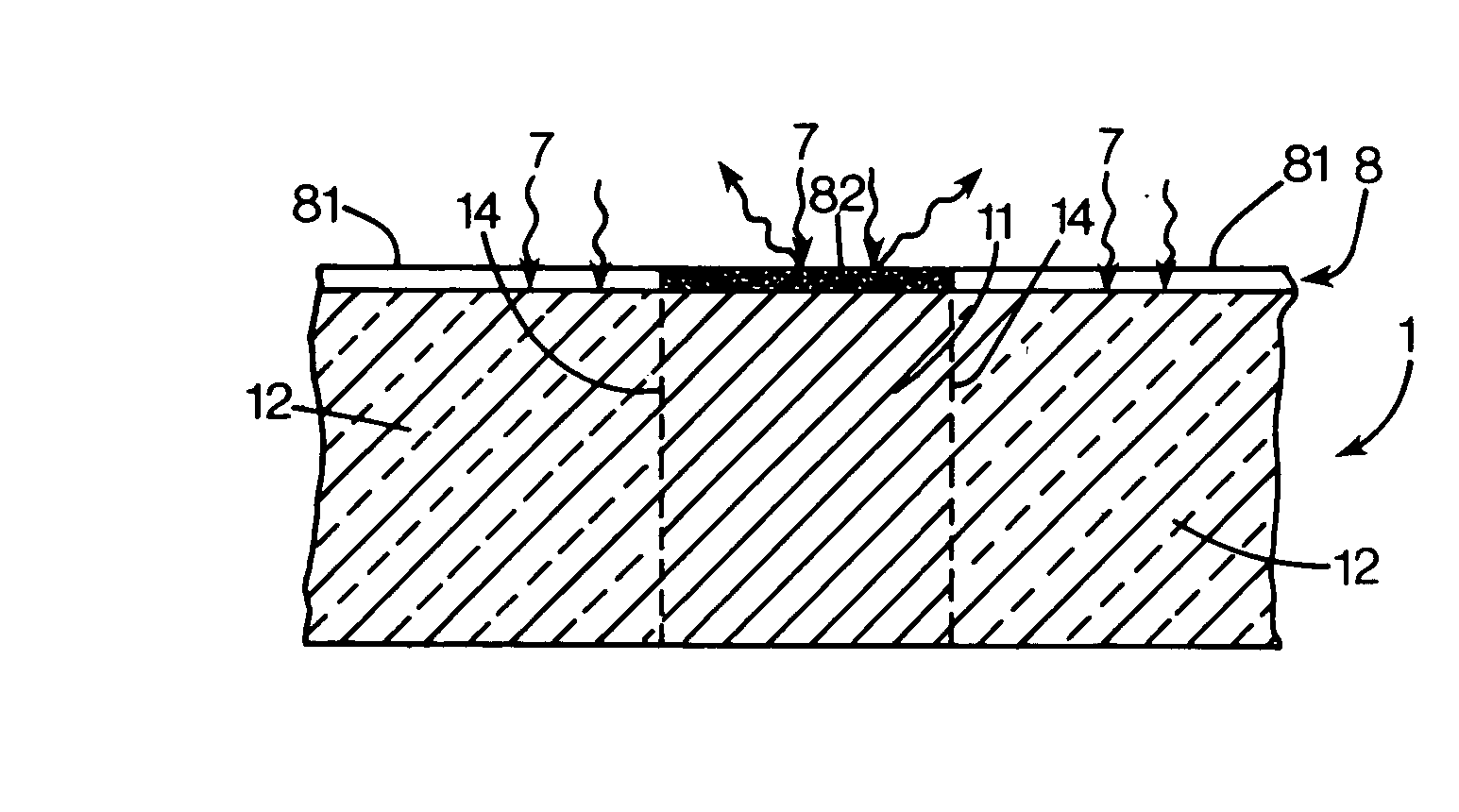
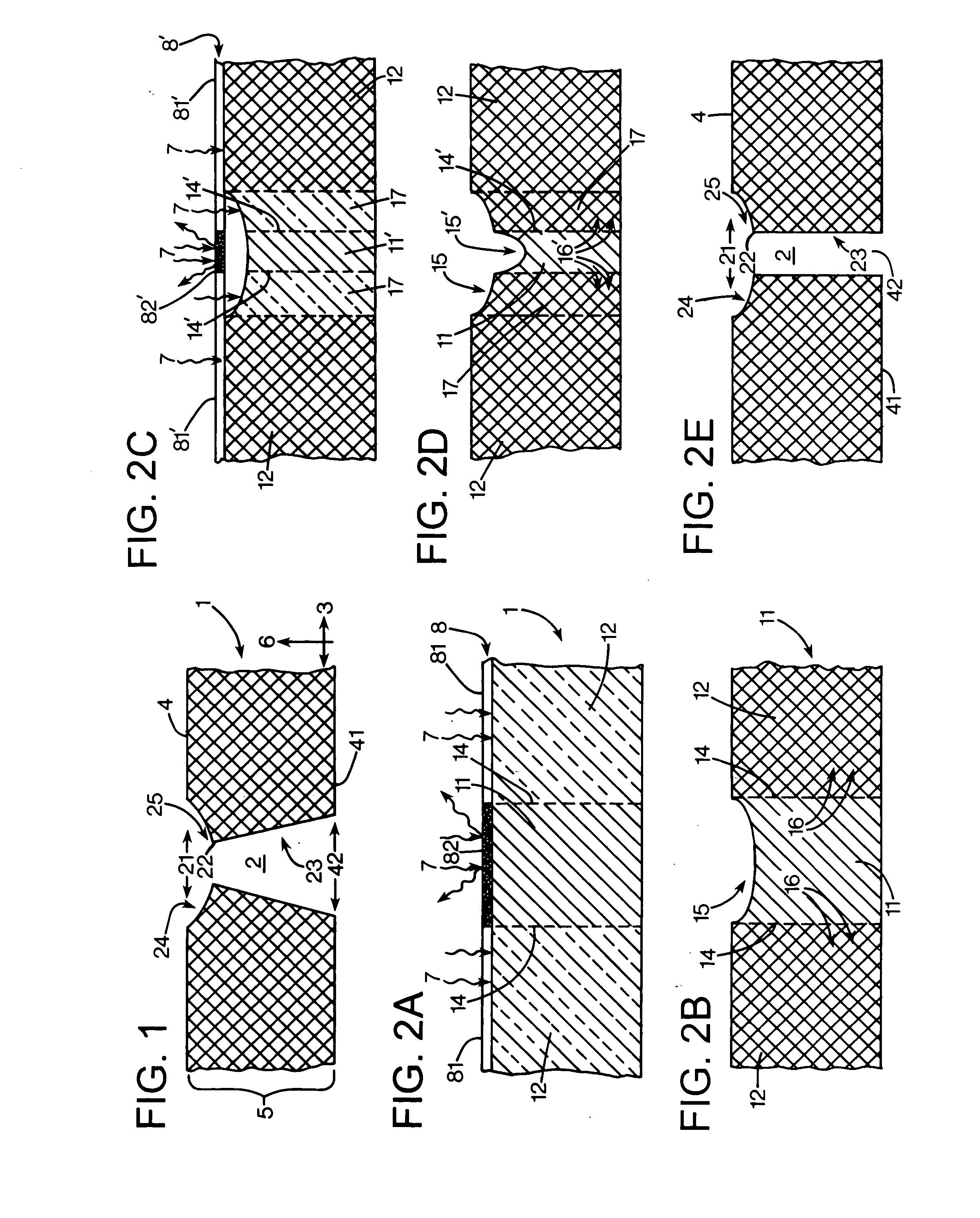
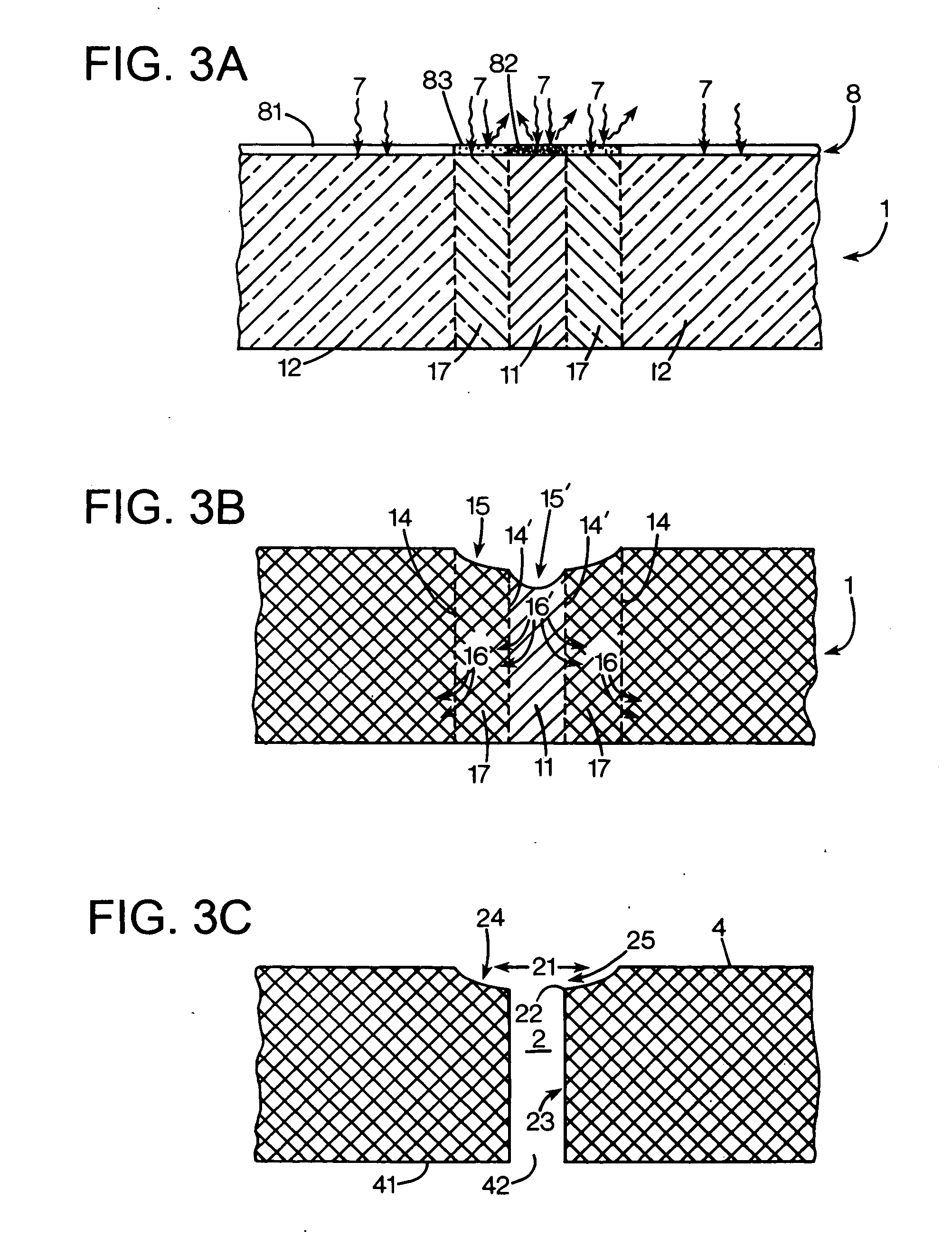
[0017]FIG. 1 illustrates an exemplary embodiment of a layer 1 of cross-linked photo-resist with a void 2 formed by an exemplary embodiment of a photo-resist etch process. The layer 1 of photo-resistive film is arranged horizontally in an x-y plane, the direction of which is shown by the arrow 3. The void extends from the upper surface 4 of the layer to a depth 5 along the z-axis 6. The upper surface opening 21 of the void 2 has a cross-sectional area, in a horizontal x-y plane, which is larger than the cross-sectional area in an x-y plane of a medial portion 22 of the void 2. In an exemplary embodiment, a lower portion 23 of the void 2 has a cross-sectional area which may be equal to or greater than the cross-sectional area of the medial portion 22.

[0018] In an exemplary embodiment, the layer of photo-resist can comprise a negative-actin...


PUM

PropertyMeasurementUnit
temperatureaaaaaaaaaa
diameteraaaaaaaaaa
glass transition temperaturesaaaaaaaaaa

Abstract

A method of forming a depression in a surface of a layer of photo-resist comprises exposing a first portion of a layer of photo-resist with a first dose of radiant energy. A second portion of the layer is exposed with a second dose of radiant energy. The second dose is less than the first dose. The layer is baked.

Description

BACKGROUND OF THE DISCLOSURE [0001] Photo-resist etching is often used to create micro-structures in micro-electronic devices. For example, photo-resist etching is used to create micro-fluidic chambers, including ink manifolds and firing chambers, in a barrier layer of a fluid ejector such as an ink-jet print head. Photo-resist etching is used to form nozzles or fluid-transfer bores in an orifice layer arranged above the barrier layer of an ink-jet print head. [0002] Counter-bores formed at the exit of a fluid-transfer bore or nozzle can reduce or prevent damage to the exit geometry of a nozzle caused by wiping and can extend the useful life of a fluid ejection device. The counter-bores can reduce or prevent, for example, ruffling of the nozzle exit and reduce or prevent fluid trajectory problems associated with puddling. Counter-bores are formed, for example, by laser ablation, which may increase production costs. [0003] Exemplary methods of forming manifolds, chambers and other fe...

Claims


Application Information

Patent Timeline
Patent Type & Authority Applications(United States)
IPC IPC(8): B01J2/14B41J2/16G03F7/00G03F7/20
CPCB41J2/16B41J2/1626B41J2/1631G03F7/2051G03F7/0015G03F7/2022B41J2002/14475G03F7/0037G03F7/20B01J2/14
Inventor SHAARAWI, MOHAMMEDSTRAND, THOMAS R.
Owner HEWLETT PACKARD DEV CO LP
Why Eureka
Try Eureka