Medical device anchor and delivery system

a technology of medical devices and anchors, applied in the field of medical technology, can solve the problems of medical implants being moved and changed, the effective positioning of such devices can prove to be a very difficult task, and the implanted device being in the desired position for an extended period of time is often more difficul

Inactive Publication Date: 2005-06-16
NITINOL DEVICES & COMPONENTS
View PDF99 Cites 117 Cited by
  • Summary
  • Abstract
  • Description
  • Claims
  • Application Information

AI Technical Summary

Benefits of technology

[0011] It is a primary object of the present invention to provide a novel and improved method for positioning and anchoring a medical implant device which includes positively propelling one or more anchors through a body wall subsequent to a medical implant device connected to the anchor reaching a desired position and coming to rest.

Problems solved by technology

Effective positioning of such devices can prove to be a very difficult task, and maintaining an implanted device in a desired position for an extended period of time is often more difficult.
Unfortunately, changes in the dimensions of the body vessel or passageway or variations in the flow of blood or other fluids there through can cause the medical implant to migrate and change position.
Otherwise, effective performance of such therapeutic devices will not be achieved.
It is often very difficult to move such a device into position with the desired orientation, and once this is achieved, it is critical that no further motion occur.
This may be acceptable for a permanent implant, but rigid hooks are not a viable option if the medical implant device is to be removed after several weeks or months.
Anchoring hooks, although effective in many instances, are subject to a number of disadvantages which can make it difficult to properly position and maintain the position of a medical implant device.
In prior devices, the anchoring hooks are engaged due to the expansion of the device into contact with the wall of a body vessel or passageway, and if the device moves from a desired position during expansion and contact with the wall occurs, the device cannot be easily repositioned.
The anchoring function of the hooks is not separable from the expansion of the device.
In cases where the operation of the hooks is tied to the expansion of a medical implant device, there can be instances where one or more of the hooks fails to properly engage the wall of a body vessel or passageway causing the device to become off center.
Sometimes movement of the device longitudinally will engage the errant hooks, but this movement can also alter the position of the device.
Also, the configuration of a hook which curves in a single direction from a shaft to a pointed end can prove to be a disadvantage.
However, there are conditions which can result in a backflow of blood in a blood vessel, and pressure on the device and the anchoring hooks resulting from such backflow can cause the hooks to back out and disengage from the vessel, thus changing the orientation of the device within the blood vessel and causing deleterious changes in the performance of the implant.
Finally, even if the hooks of an implant device are properly engaged with a vessel wall, there are conditions which result in the subsequent outward expansion of the vessel wall to an extent where the hooks tend to become disengaged.

Method used


Image

  • Medical device anchor and delivery system
  • Medical device anchor and delivery system
  • Medical device anchor and delivery system

Examples


Embodiment Construction

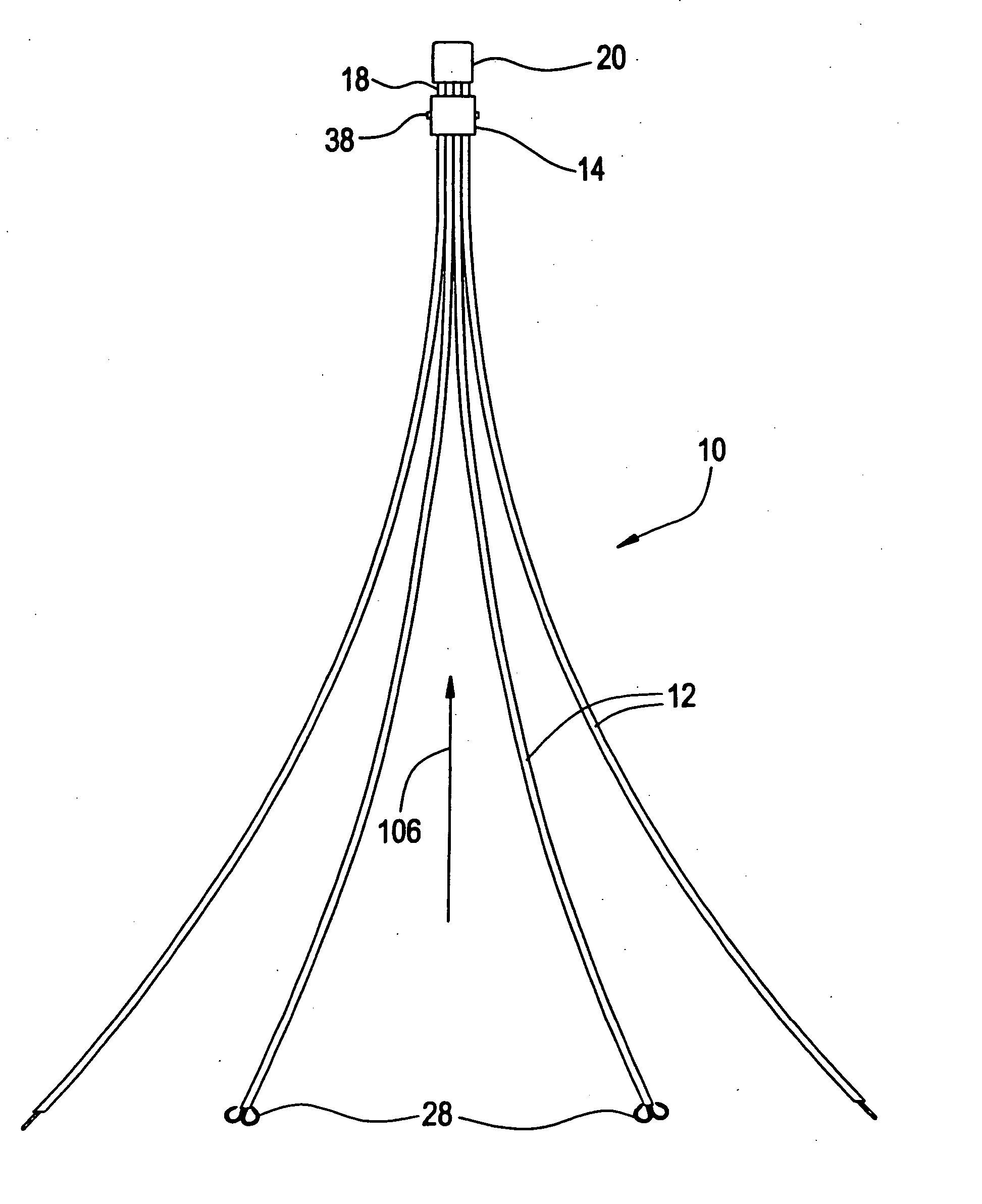
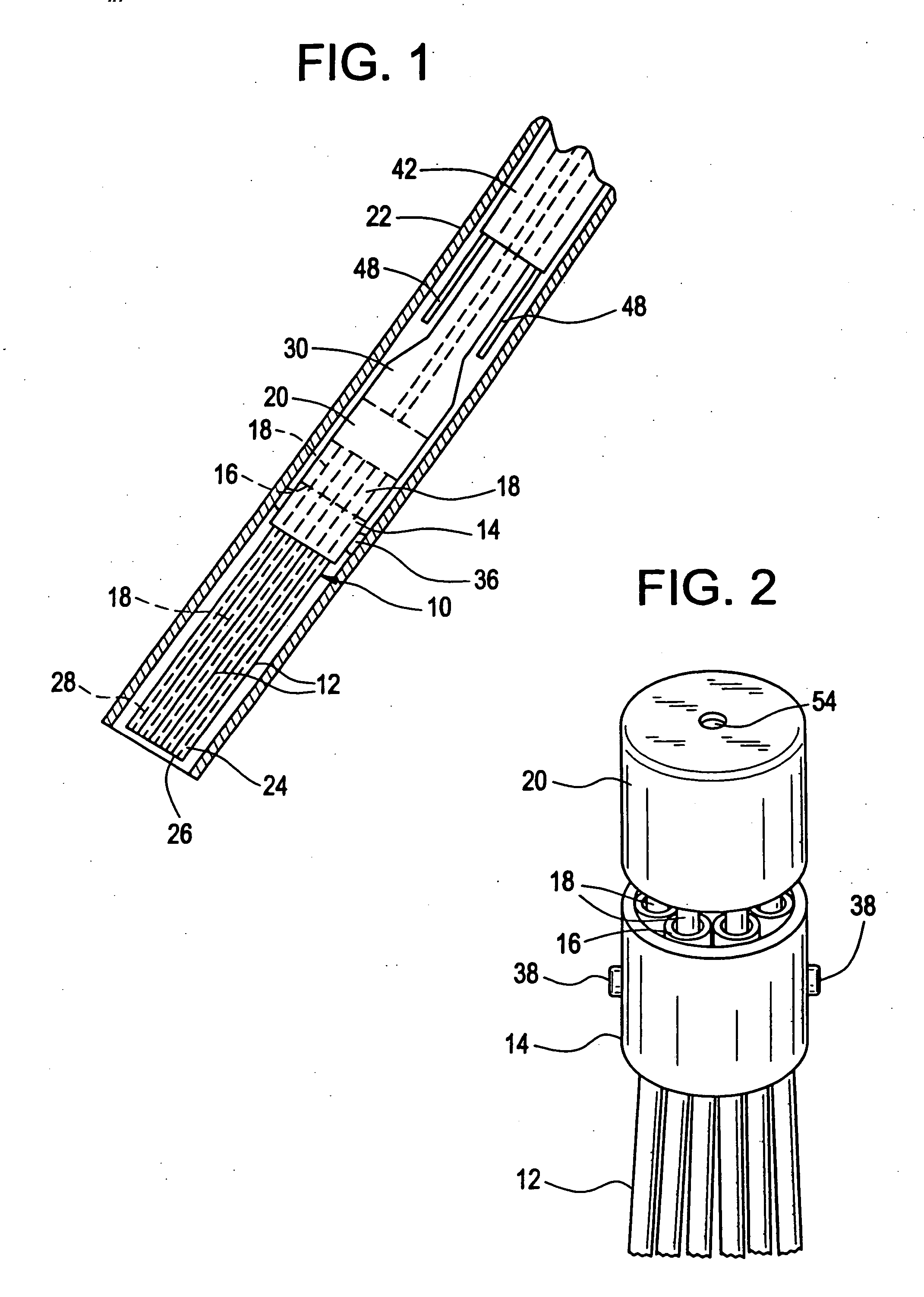
[0040] Referring to FIGS. 1-2, a blood clot filter which includes anchors in accordance with the present invention is illustrated generally at 10. This filter, shown for illustration as a vena cava filter, is formed with a plurality of elongate legs 12 which are secured to, and extend outwardly from a leg retention sleeve 14. The elongate legs are formed by small, open ended tubes each having a first open end 16 which opens at the leg retention sleeve. A plurality of long anchor shafts 18 are attached at a distal end to an anchor support hub 20 which is spaced from the leg retention sleeve when the vena cava filter is collapsed within a catheter or delivery tube 22. Each shaft 18 extends from the anchor support hub 20 into the first open end 16 of a tubular leg 12 and through the leg to a distal end 24 at a point adjacent to a second open end 26 of the tubular leg. An anchor 28 is formed at the distal end of each shaft 18 in a manner to be described.

[0041] The elongate legs 12 and ...


PUM


Abstract

A method and apparatus for anchoring a medical implant device after the device has been brought to rest at a desired position within a blood vessel or other body passageway. An anchor delivery system is provided which houses one or more uniquely configured expandable anchors which are connected to the medical implant device. The anchors remain housed in a non expanded configuration until after the medical implant device has come to rest in a desired position within the body, and then the anchors are positively propelled through a body wall from a first side to a second side where each anchor expands outwardly from an anchor shaft. In one configuration, the anchors are each formed in the shape of a compressible closed loop which extends outwardly from an anchor shaft and loops back to cross over and extend beyond the anchor shaft. To positively propel the anchors, a drive shaft for the anchor shafts extends back to a triggering unit which, when activated, causes the drive shaft to drive the anchor shafts in a direction which results in propulsion of the anchors through the body wall.

Description

[0001] This application is a Continuation-in-Part application of Ser. No. 10 / 705,226 filed Nov. 12, 2003.BACKGROUND OF THE INVENTION [0002] Recent advances in medical technology have resulted in the development of a variety of medical devices for permanent or temporary implantation in the human body. Effective positioning of such devices can prove to be a very difficult task, and maintaining an implanted device in a desired position for an extended period of time is often more difficult. This is particularly true if the implanted device is to remain only temporarily and is designed to facilitate subsequent removal. [0003] A number of medical implant devices are designed to collapse for insertion within a catheter or other delivery unit and to expand to a predetermined shape when ejected after delivery. Many of these self expanding devices rely primarily upon the contact between the device and the wall of a body vessel or passageway to maintain the device in position after the delive...

Claims


Application Information

Patent Timeline
Patent Type & Authority Applications(United States)
IPC IPC(8): A61B17/12A61B17/14A61B17/32A61F2/01A61M29/00
CPCA61B17/12022A61B17/12109A61B17/12172A61F2/01A61B2017/12095A61F2230/005A61F2230/0078A61B2017/12054A61F2002/016A61F2/0105
Inventor KLESHINSKI, STEPHEN J.RAVENSCROFT, ADRIAN
Owner NITINOL DEVICES & COMPONENTS
Why Eureka
Try Eureka