Intake system structure for vehicle

a technology for a vehicle and an intake system, which is applied in the direction of machines/engines, combustion air/fuel air treatment, cycle equipment, etc., can solve the problems of not easy to raise the intake efficiency, and achieve the effect of simple attachment, and reducing the number of parts

Active Publication Date: 2005-06-23
HONDA MOTOR CO LTD
View PDF11 Cites 14 Cited by
  • Summary
  • Abstract
  • Description
  • Claims
  • Application Information

AI Technical Summary

Benefits of technology

[0018] According to the fourth aspect of the invention, since the intake opening is open toward a side of the vehicle body, the intake path can be shortened as far as possible by introducing external air from the sideward direction of the vehicle body. Because the intake opening is provided on the side face, it cannot be observed readily. Thus, good appearance can be maintained.
[0019] According to the fifth aspect of the invention, since the dust cover is attached between the left and right vehicle body frames making use of the support brackets of the vehicle body frames and the projection of the connecting tube, the dust cover can be attached more simply without increasing the number of parts very much.
[0020] According to the sixth aspect of the invention, since the intake opening is formed from the cutaway portion provided in an opposing relationship to the wheel well, the intake opening can be formed readily at a position at which it can be observed c

Problems solved by technology

Where air is taken in from forwardly of the vehicle body, a long intake air p

Method used


Image

  • Intake system structure for vehicle
  • Intake system structure for vehicle
  • Intake system structure for vehicle

Examples


Embodiment Construction

[0040] In the following, an embodiment wherein the present invention is applied to a four-wheeled buggy is described. It is to be noted that, in the present application, the forward and backward, leftward and rightward, and upward and downward directions are given with reference to the vehicle body when the vehicle is in a state traveling forward.

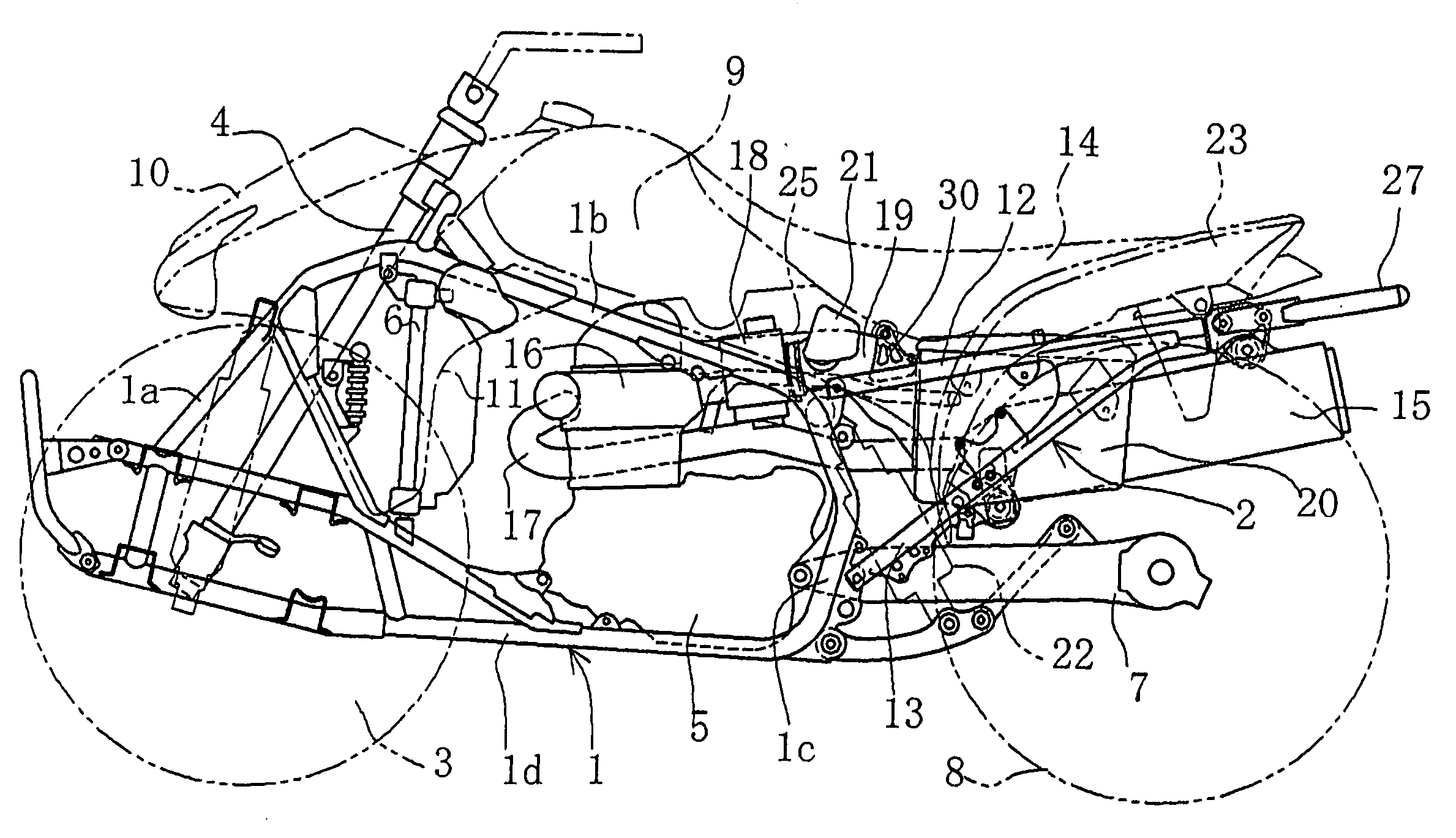
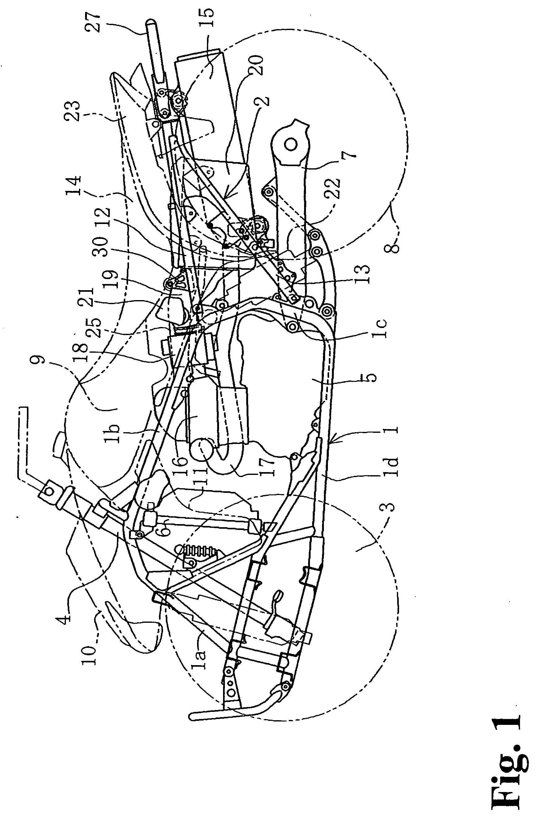
[0041]FIG. 1 is a side elevational view of a four-wheeled buggy, and a vehicle body frame includes a main frame 1 having a substantially closed loop shape as viewed in side elevation, and a rear frame 2 having a truss structure of a substantially triangular shape as viewed in side elevational and extending rearwardly from the main frame 1.

[0042] The main frame 1 is formed from a pipe member made of a suitable metal such as a light alloy and includes a front pipe 1a, an upper pipe 1b, a pivot pipe 1c and a lower pipe 1d. Front wheels 3 are supported on the left and right of a front portion of the main frame 1 and are steered by a steering ...


PUM


Abstract

A four-wheeled buggy includes a shortened air intake path so that intake efficiency is improved. An air cleaner is disposed in a space surrounded on the left and right by a rear fender below a seat, and a space surrounded by the air cleaner, the seat and left and right portions of the rear fender is formed as an intake air path. A cutaway portion is provided on a side face of the rear fender connecting to a seat rail and is formed as an intake opening communicating outwardly sidewardly such that it is communicated with the intake air path on the inner side. External air taken in from the intake opening enters the intake path and is immediately introduced into the inside of the air cleaner through an intake duct.

Description

FIELD OF THE INVENTION [0001] This invention generally relates to an intake structure suitable for a vehicle such as a four-wheeled buggy, and more particularly to an intake structure wherein an intake air path is shortened to improve the intake efficiency. BACKGROUND OF THE INVENTION [0002] In general, an intake structure for a four-wheeled buggy is known wherein an intake air path is formed between a fuel tank and a tank cover which covers the fuel tank. An intake structure of this type takes in external air from an intake opening provided at a comparatively high position forwardly of a vehicle body. The air is then introduced into an air cleaner below a seat through the intake air path. One example of such an intake structure is disclosed in Japanese Patent No. 2,534,228. [0003] Where air is taken in from forwardly of the vehicle body, a long intake air path is required, and therefore, it is not easy to raise the intake efficiency. In addition, it is necessary to assure a space f...

Claims


Application Information

Patent Timeline
IPC IPC(8): B62J15/00B62J23/00B62J99/00B62K5/00B62K5/01F02M35/16
CPCF02M35/02F02M35/1233F02M35/162F02M35/048
Inventor NAKANO, NOBUHIKOYAMASHITA, AKIHIRO
Owner HONDA MOTOR CO LTD
Why Eureka
Try Eureka