

Door frame of a shaft door with a control arrangement for an elevator shaft and method for access to a control unit
- Summary
- Abstract
- Description
- Claims
- Application Information
AI Technical Summary
Benefits of technology
Problems solved by technology
Method used
Image

Examples
Embodiment Construction
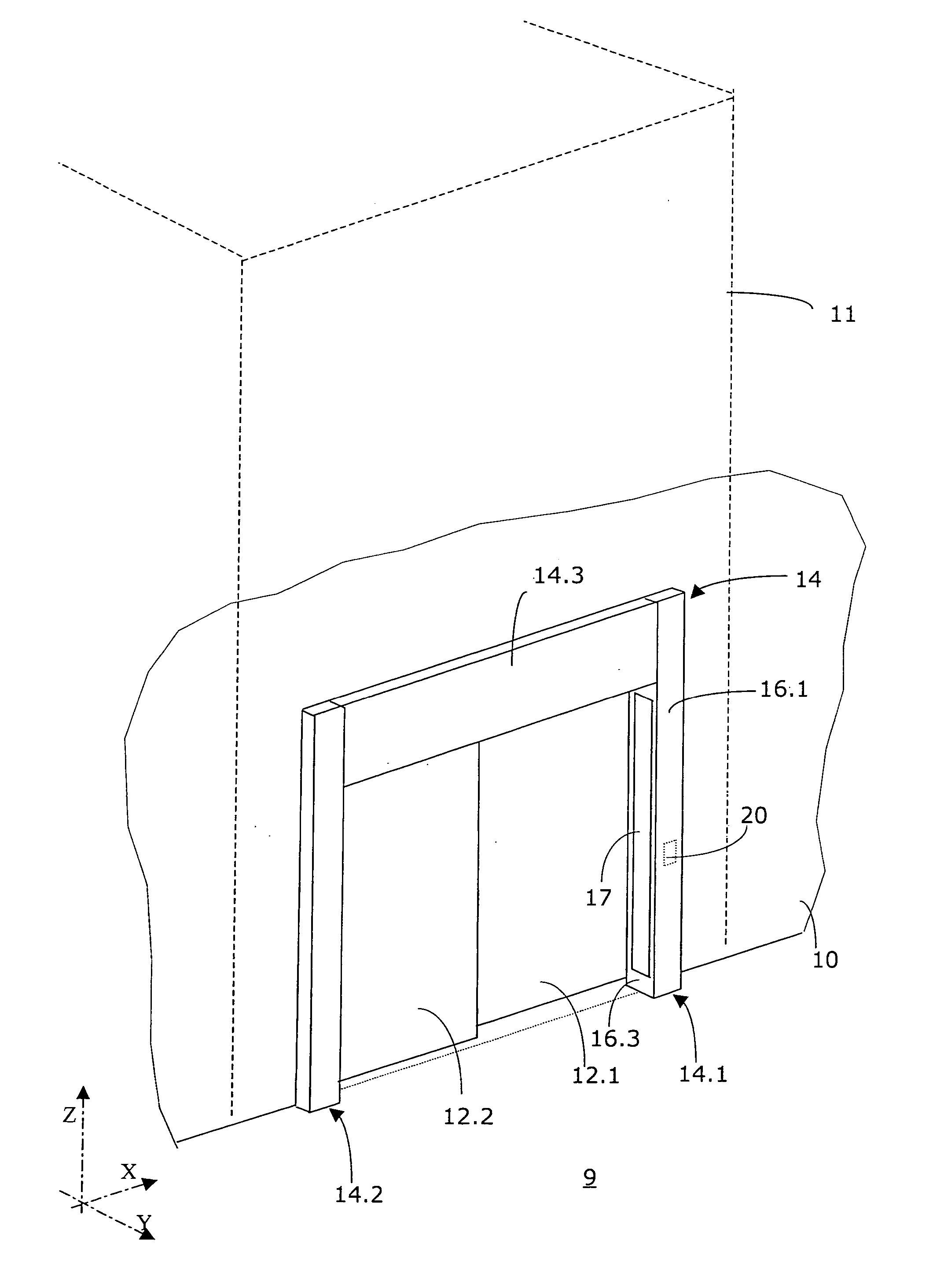
[0025] The aspect of an elevator installation, as offered to a user thereof located on a floor 9, is illustrated in FIG. 1. A building, which is not further illustrated and in which the elevator installation is located, comprises a building wall 10 which bounds an elevator shaft 11 indicated in FIG. 1 by dashed lines.
[0026] The elevator shaft 11 is separated from the floor 9 visible in FIG. 1 by an elevator shaft closure. The elevator shaft closure comprises a shaft door which substantially consists of two door leaves 12.1, 12.2 and a door frame 14. The door leaves 12.1, 12.2 are horizontally displaceable and, in particular, in the direction of an axis “X” of an orthogonal three-dimensional co-ordinate system shown in FIG. 1 and with the further axes “Y” and “Z”. The door frame 14 comprises three door frame elements, namely two lateral, vertical door frame elements 14.1, 14.2 which form door posts and are oriented parallel to the axis “Z”, and an upper, horizontal door frame elemen...
PUM
 Abstract
Description
Claims
Application Information