Paper-back tape dispenser

a tape dispenser and paper back technology, applied in the field of paper back tape dispensers, can solve the problems of excessive waste, difficult back insulation, time-consuming,

Active Publication Date: 2005-06-23
METZGER BRIAN DAVID
View PDF3 Cites 14 Cited by
  • Summary
  • Abstract
  • Description
  • Claims
  • Application Information

AI Technical Summary

Benefits of technology

[0010] Longitudinally aligned and attached to the rear surface of the back plate is a hollow short pipe. Located inside the pipe is a sliding piston that acts as a stabilizer for the axle discussed further below. Formed on opposite sidewalls of the short pipe are two longitudinally aligned slots. Perpendicularly aligned and extending transversely through the pipe, through the two slots, and through the piston is an axle. The axle is off-centered on the pipe so that the length of the section of axle that extends into the cavity is sufficient to length to extend into the center hole on a spool of tape placed into the cavity. The axle is sufficient in diameter so that a spool placed into the center hole on a roll of tape may rotate freely thereon on the axle. The opposite end of the axle extends outward through the outside surface of the pipe. Suitable nuts and washers are used to securely hold the spool on the axle. During use, the portion of the axle that extends outside the pipe is a finger bar that is used to lift the axle relative to the pipe so that the new roll of tape may be placed over the axle and into the cavity.
[0011] A spring is disposed inside the short pipe and biased between the top surface of the pipe and the top surface of the axle. During operation, the spring constantly forces the axle upward in the pipe so that the upper surface of a roll of tape is automatically pressed against the upper, inside, surface of the outer shell thereby preventing the roll from unraveling.

Problems solved by technology

Because a roll of tape is relatively large and is usually held in one hand when used, unwinding the roll to dispense the desired amount of tape, cutting the tape, the removing the paper back layer, and then evenly applying the tape over the desired joint and layer of foil or vinyl back insulation can be difficult and time consuming.
Because the adhesive may fold back onto itself, excessive waste can result.
These problems are compounded when the ductwork is located in restricted or confined work areas.
All three types of tape products are difficult to tear or rip with the user's hands.
Even when great care is taken to prevent unraveling, workers often spend a considerable amount of time rewinding rolls of tape after each use.

Method used


Image

  • Paper-back tape dispenser
  • Paper-back tape dispenser
  • Paper-back tape dispenser

Examples


Embodiment Construction

)

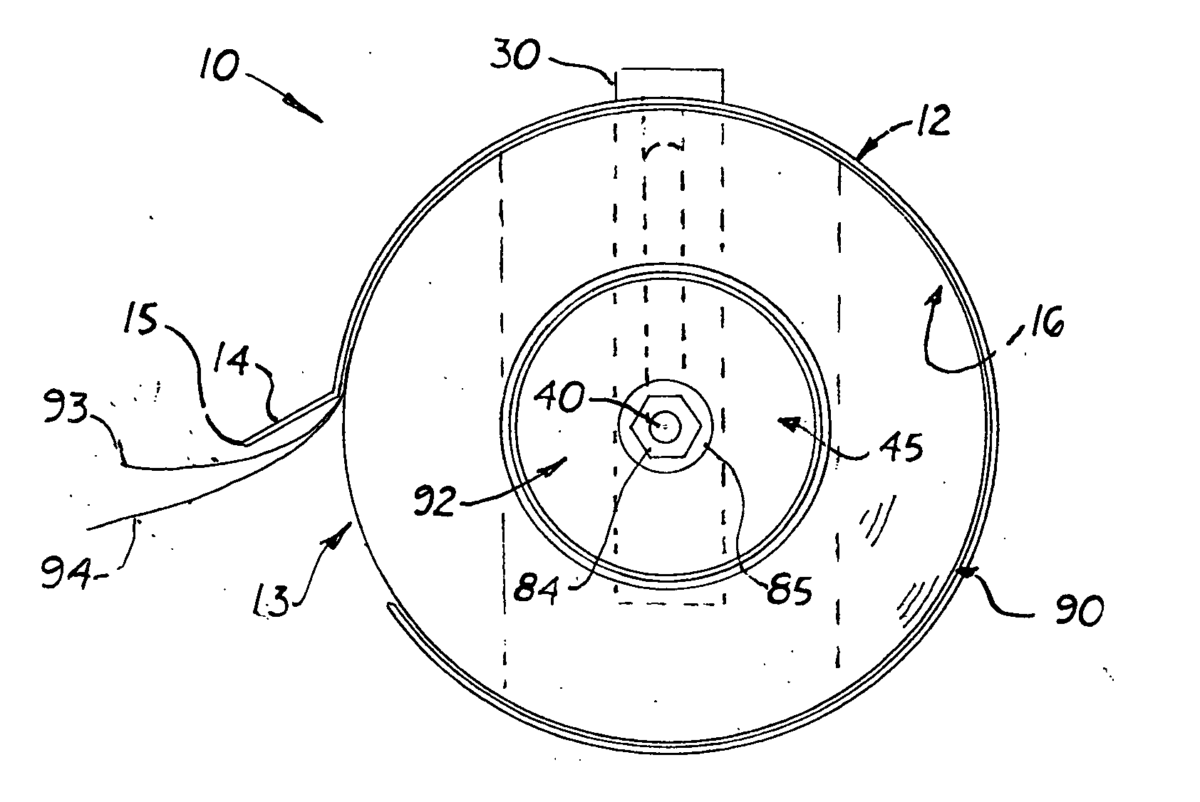
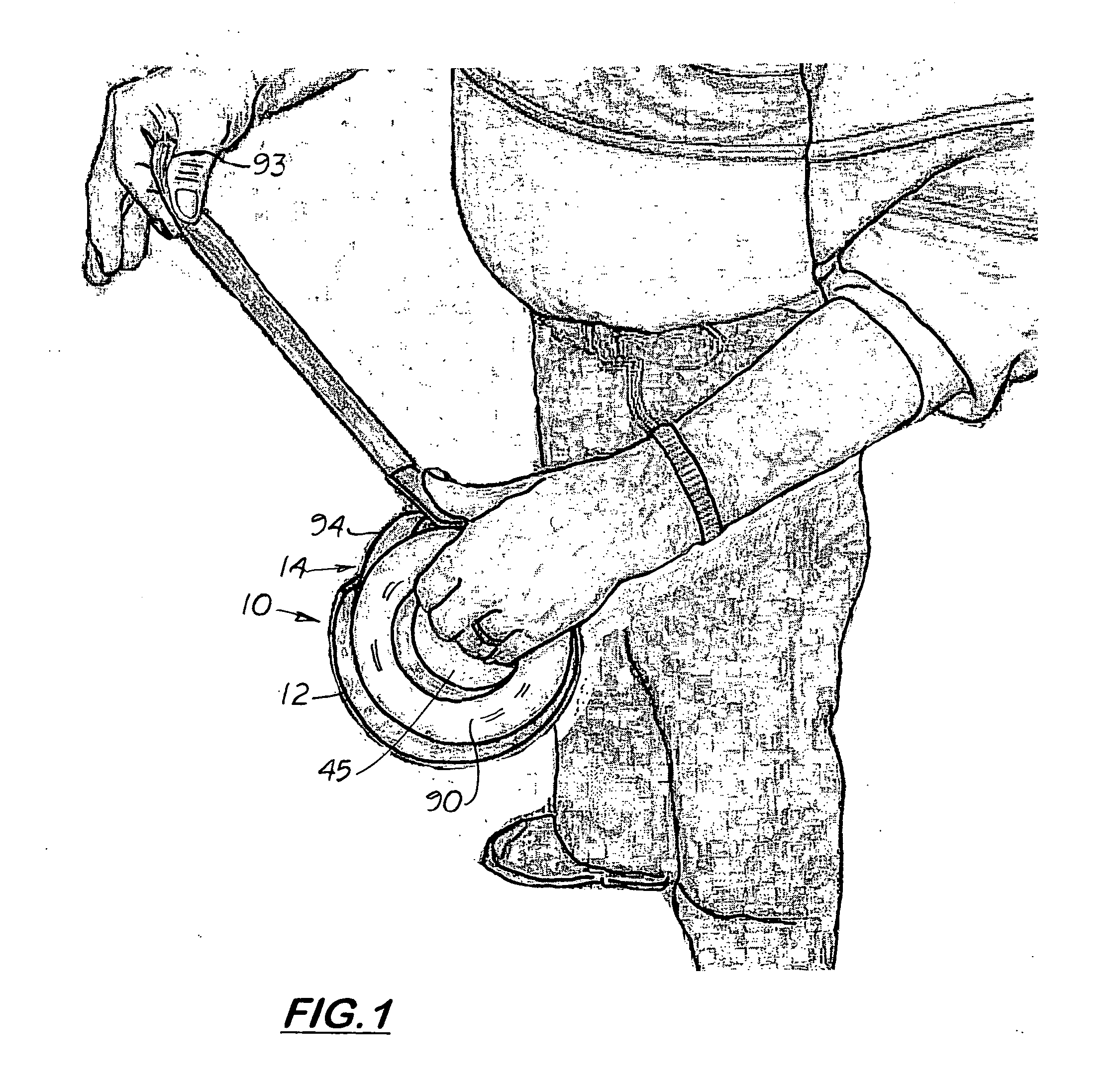
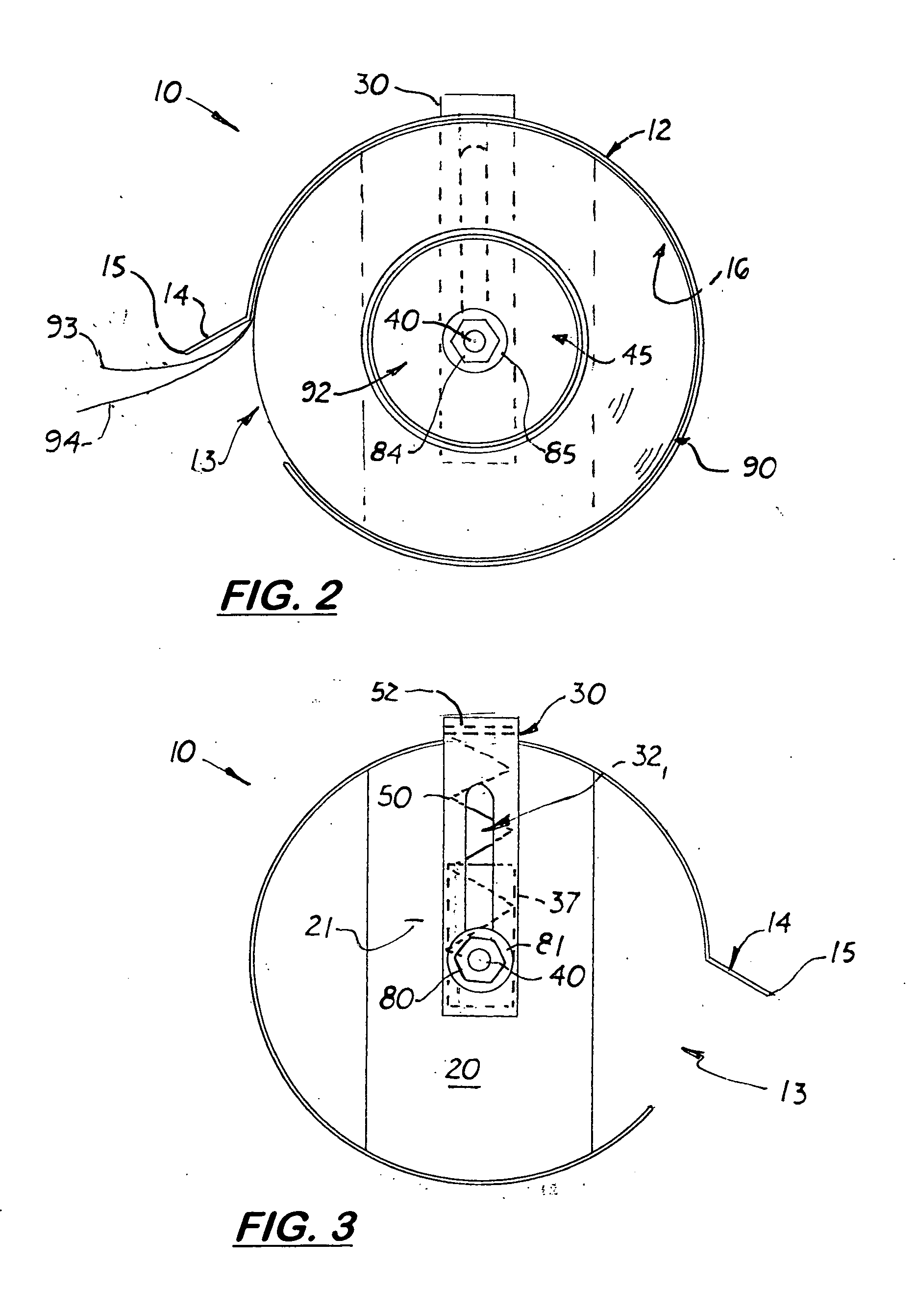
[0020] Referring to the Figs., there is shown a paper back tape dispenser, 10 that includes a a cylindrical outer shell 12 made of sheet metal attached to an optional, transversely aligned back plate 20. Formed on one side of the outer shell 12 is a side opening 13 with a forward extending lip 14 with a distal serrated cutting edge 15 formed thereon. The back plate 20 is securely attached to the back edge of the outer shell 12 thereby forming a cylindrical cavity 16 inside the outer shell 12 capable of receiving a roll of tape 90.

[0021] Longitudinally aligned and attached to the rear surface 21 of the back plate 20 is a hollow short pipe 30. Formed on the inside and outside surfaces of the short pipe 30 are two longitudinally aligned slots 32, 34. Located inside the short pipe 30 is a cylindrical shaped sliding piston 37. The sliding piston 37 is hollow and opened at its opposite ends and slightly smaller in diameter than the pipe 30. During operation, the piston 37 slides freely ...


PUM


Abstract

A paper back tape dispenser that includes a cylindrical outer shell with a center cavity designed to receive a standard roll of paper back tape. The outer shell includes a side opening with a forward extending lip. Formed on the distal edge of the lip is a serrated cutting edge. Aligned and attached to the rear surface of the outer shell is a hollow pipe Formed on the inside and outside surfaces of the short pipe are two longitudinally aligned slots. Located inside the short pipe is a sliding piston. Extending through the piston and the pipe is an axle that partially extends into the cavity to hold a spool that fits inside a roll of tape. A spring is disposed inside the pipe that automatically holds the axle in an upward position on the pipe. During use, the portion of the axle that extends outward acts as a finger bar that is used to lift the axle upward so that new, large roll of tape may be placed over the axle and into the cylindrical cavity.

Description

BACKGROUND OF THE INVENTION [0001] This Utility Patent Application is based on Provisonal Patent Application (Ser. No. 60 / 531,267) filed Dec. 22, 2003. [0002] 1. Field of the Invention [0003] This invention relates to tape dispensers, and more particularly, to tape dispensers used with adhesive tape that uses a paper layer that is removed prior to application. [0004] 2. Description of the Related Art [0005] There are three types of paper back tapes commonly used in the HVAC industry. The first one is a vinyl tape product made by Nashua Corporation of Nashua, N.H. (Product No. NAS-8223). The second is a foil packed tape product also sold by Nashua Corporation (Product No. NAS-323). A third is a reinforced packed tape product also sold by Nashua Corporation (Product No. NAS-FSK-3). All three types of tape are approximately 3 inches in width and distributed in rolls approximately 6 inches in diameter. Typically approximately 30 yards of tape are rolled onto a center spool approximately...

Claims


Application Information

Patent Timeline
Patent Type & Authority Applications(United States)
IPC IPC(8): B65H16/00B65H23/08B65H35/00B65H37/00
CPCB65H35/0033E04F21/165B65H37/005E04F21/1657Y10T225/246Y10T225/238
Inventor METZGER, BRIAN DAVID
Owner METZGER BRIAN DAVID
Why Eureka
Try Eureka