Contactless power transmitting device

a transmission device and contactless technology, applied in the direction of electric vehicles, transportation and packaging, electric generators, etc., can solve the problems that the conventional contactless transmission device cannot cope with this situation easily and promptly, and cannot be used by cellular phones, so as to improve safety or fraud prevention, the effect of easy and quick respons

Active Publication Date: 2005-06-23
138 EAST LCD ADVANCEMENTS LTD
View PDF7 Cites 138 Cited by
  • Summary
  • Abstract
  • Description
  • Claims
  • Application Information

AI Technical Summary

Benefits of technology

[0030] According to the above-mentioned aspects of the invention, in the case in which a power supply for a cellular phone or portable personal computer runs out when a user is away from his or her office and the power sup

Problems solved by technology

Unfortunately, a cellular phone cannot be used after it runs out of power (loses the charge in its power supply).
The conventional contactless power transmitting device cannot cope easily and promptly with this situation.
However, in the case in which the power transmitting circuit 2 starts operation in condition

Method used


Image

  • Contactless power transmitting device
  • Contactless power transmitting device
  • Contactless power transmitting device

Examples


first embodiment

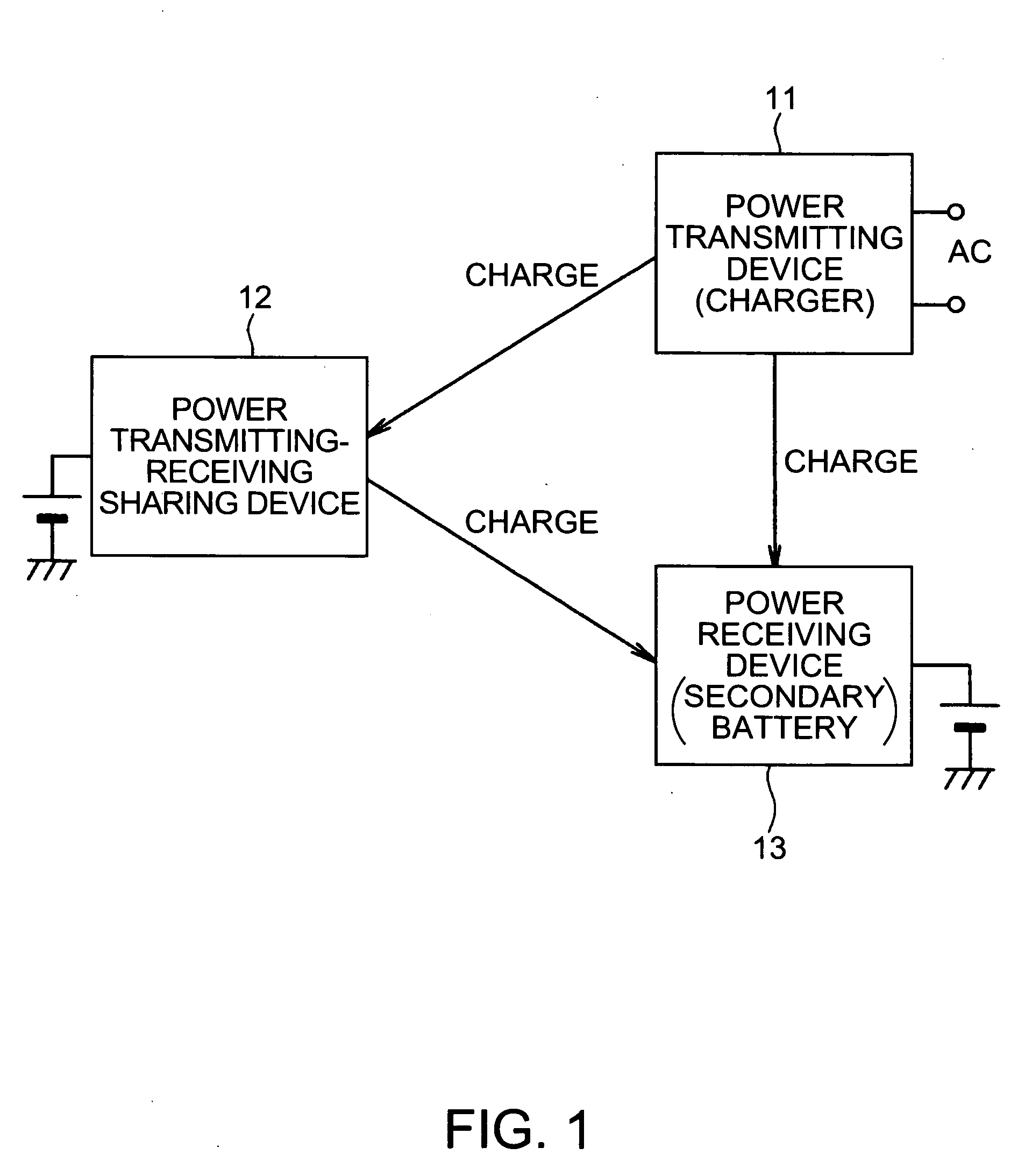
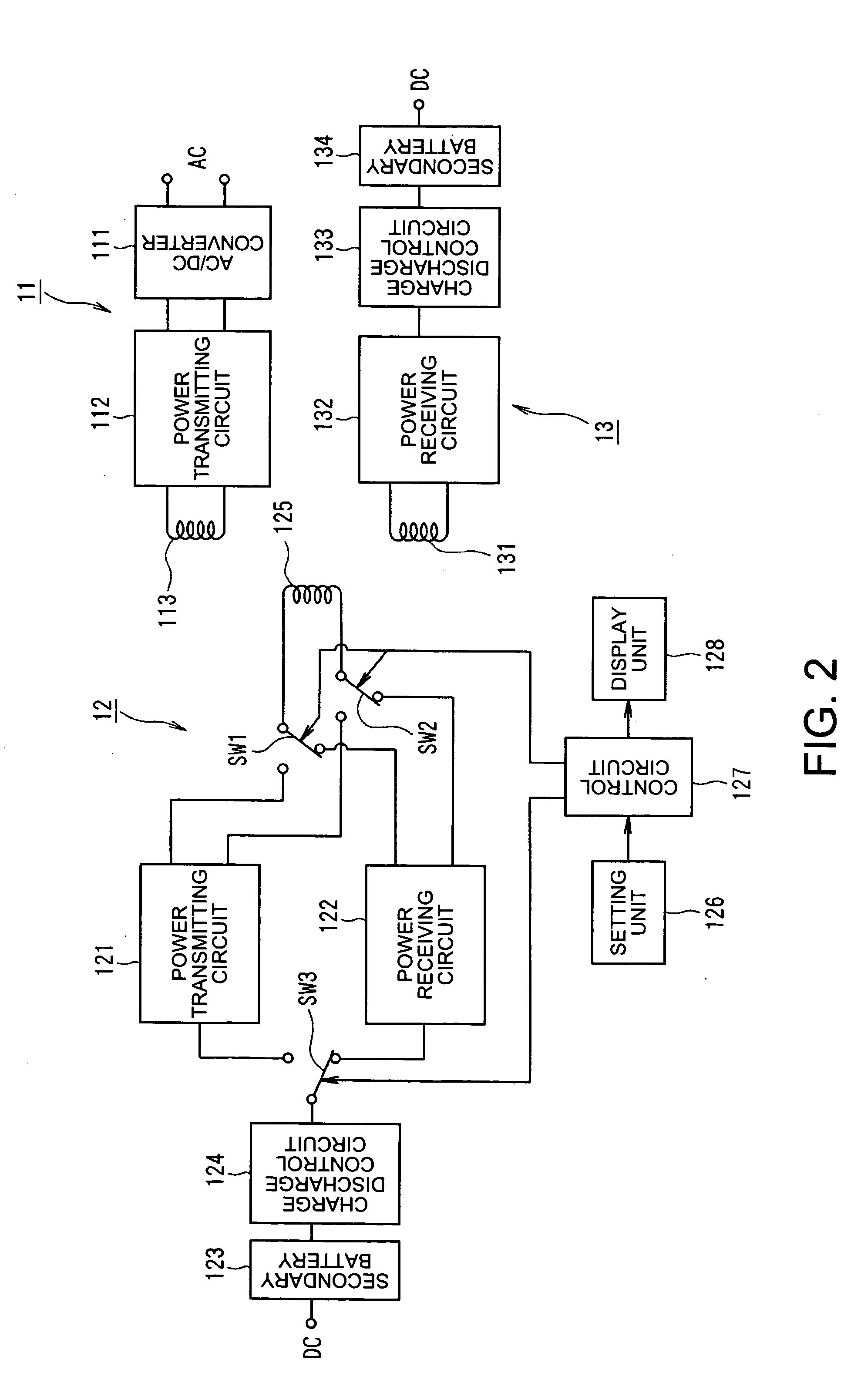
[0040] A configuration of a contactless power transmitting device of the present invention will be explained with reference to FIGS. 1 and 2.

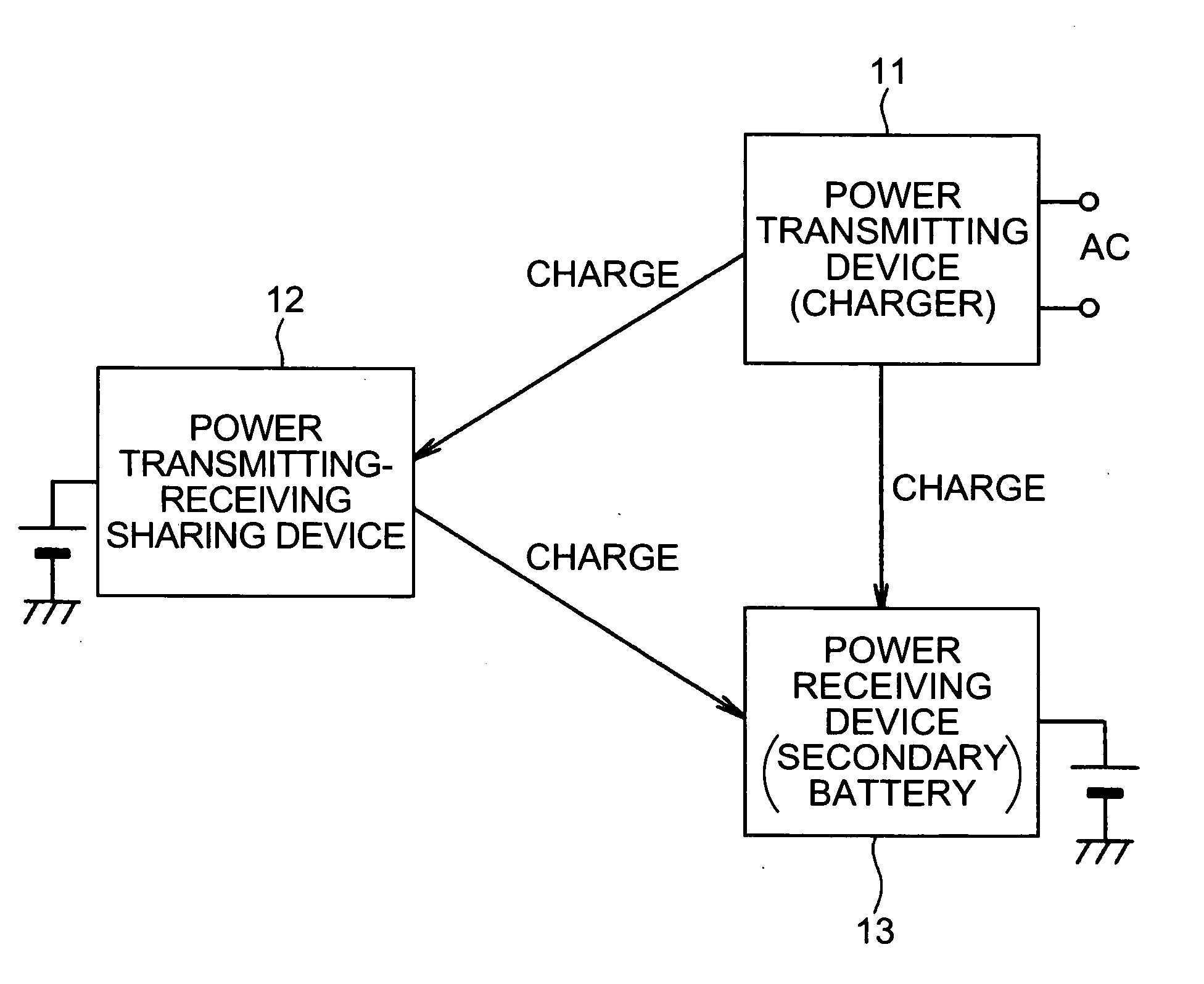
[0041] As shown in FIG. 1, the contactless power transmitting device of the first embodiment includes a power transmitting device 11 functioning as a charger, a power transmitting-receiving sharing device 12 functioning as a charger and including a secondary battery, and a power receiving device 13 including a secondary battery.

[0042] The power transmitting device 11 is electromagnetically coupled to the power transmitting-receiving sharing device 12 or the power receiving device 13 so as to form the contactless power transmitting device respectively. If the power transmitting device 11 is coupled to the power transmitting-receiving sharing device 12, the power transmitting device 11 charges the secondary battery included in the power transmitting-receiving sharing device 12. If the power transmitting device 11 is coupled to the power receivin...

second embodiment

[0079] Next, A configuration of a contactless power transmitting device of the present invention will be explained with reference to FIG. 4.

[0080] As shown in FIG. 4, a contactless power transmitting device of the second embodiment includes a power transmitting device 21 functioning as the charger, a power receiving device 22 including a secondary battery 223, and a transformer 23 electromagnetically coupling the power transmitting device 21 and the power receiving device 22. When the power transmitting device 21 charges the secondary battery in the power receiving device 22, an improvement in safety and fraud prevention of the charging operation can be achieved.

[0081] Here, the power receiving device 22 is used, for example, as the power supply for cellular phones, portable computers, and the like.

[0082] As shown in FIG. 4, the power transmitting device 21 includes an AC / DC converter 211, a power transmitting circuit 212, an operation start switch 213, a transformer 214, a sensor...

third embodiment

[0099] Next, a configuration of a contactless power transmitting device of the present invention will be explained with reference to FIG. 5.

[0100] In the second embodiment shown in FIG. 4, as above-mentioned, safety and fraud prevention in the charging operation of the power transmitting device 21 can be achieved. However, since a fee for the charging operation cannot be collected from users, the device cannot be used in a gas station or the like.

[0101] As shown in FIG. 5, the third embodiment includes a power transmitting device 21A functioning the charger, a power receiving device 22A including a secondary battery, a transformer 23 electromagnetically coupling the power transmitting device 21A and the power receiving device 22A. If the power transmitting device 21A charges the secondary battery in the power receiving device 22A, the charging operation can correctly be performed and a fee for the charging operation can be collected from users, thereby enabling the device to be ins...


PUM


Abstract

A contactless power transmitting device is provided including a power transmitting device functioning as a charger, a power transmitting-receiving sharing device functioning as a charger and including a secondary battery, and a power receiving device including a secondary battery. The power transmitting-receiving sharing device is used as a power supply for portable computers. The power receiving device is used as a power supply for cellular phones. The power transmitting device forms a contactless power transmitting device respectively by electromagnetically coupling to either the power transmitting-receiving sharing device or the power receiving device to charge the secondary battery or the secondary battery. The power transmitting-receiving sharing device forms the contactless power transmitting device by electromagnetically coupling to the power receiving device. In this case, the power transmitting-receiving sharing device charges the secondary battery included in the power receiving device.

Description

RELATED APPLICATIONS [0001] This application claims priority to Japanese Patent Application No. 2003-375757 filed Nov. 5, 2003 which is hereby expressly incorporated by reference herein in its entirety. BACKGROUND [0002] 1. Field of the Invention [0003] The present invention relates to a contactless power transmitting device that includes a power transmitting circuit and a power receiving circuit which are both electromagnetically coupled by a transformer and can charge a secondary battery by utilizing an output electric power of the power receiving circuit [0004] 2. Related Art [0005] As shown in FIG. 8, a device including an alternating current / direct current (AC / DC) converter 1, a power transmitting circuit 2, a transformer 5 having a primary coil 3 and a secondary coil 4, a power receiving circuit 6 and a secondary battery 7 is known as a kind of contactless power transmitting device. Further, the primary coil 3 and the second coil 4 that are included in the transformer 5 are us...

Claims


Application Information

Patent Timeline
IPC IPC(8): H01M10/46H02J7/00
CPCH02J7/025H02J7/0054H02J7/342H02J50/40H02J50/10
Inventor TAKAGI, TSUTOMUISHIZAWA, KOJI
Owner 138 EAST LCD ADVANCEMENTS LTD
Why Eureka
Try Eureka