Optical scanning unit

a scanning unit and optical technology, applied in the field of optical scanning units, can solve the problem that the optical path length between the beam deflector and the exposed object is too small to allow the optical arrangement of four group f- lenses, and achieve the effect of stable optical performance and convenient fabrication

Active Publication Date: 2005-06-23
HEWLETT PACKARD DEV CO LP
View PDF2 Cites 1 Cited by
  • Summary
  • Abstract
  • Description
  • Claims
  • Application Information

AI Technical Summary

Benefits of technology

[0011] An embodiment of the present invention provides an optical scanning unit employing an f-θ lens with a low magnification of focusing in subscanning direction and which is able to provide a long optical path between a beam deflector and an exposed object as well as stable optical performance and facilitate ease of fabrication.

Problems solved by technology

When the optical scanning unit having a single beam deflector scans multiple beams, an optical path length between the beam deflector and the exposed object is too small to allow optical arrangement of four group f-θ lenses.

Method used


Image

  • Optical scanning unit
  • Optical scanning unit
  • Optical scanning unit

Examples


Embodiment Construction

[0022] Reference will now be made in detail to embodiments of the present invention, examples of which are illustrated in the accompanying drawings, wherein like reference numerals refer to the like elements throughout. The embodiments are described below in order to explain the present invention by referring to the figures.

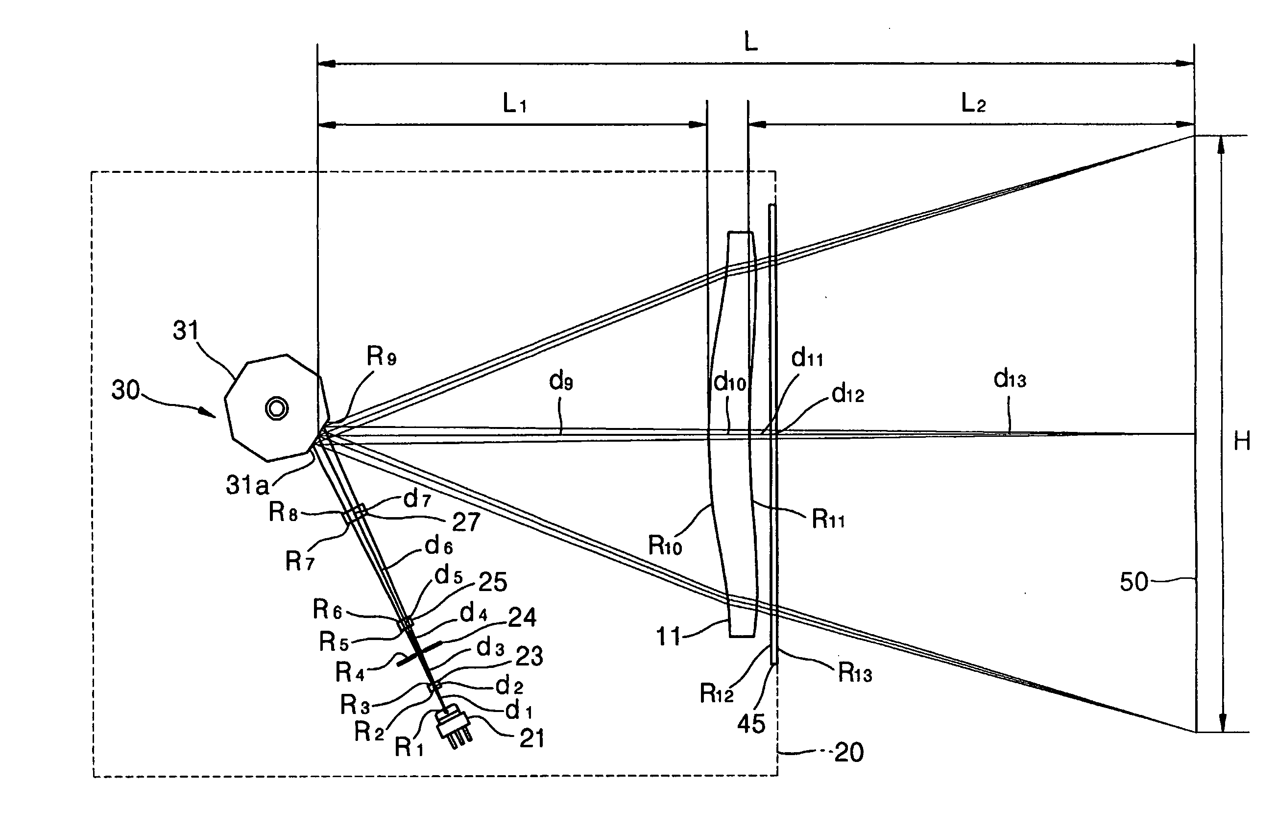
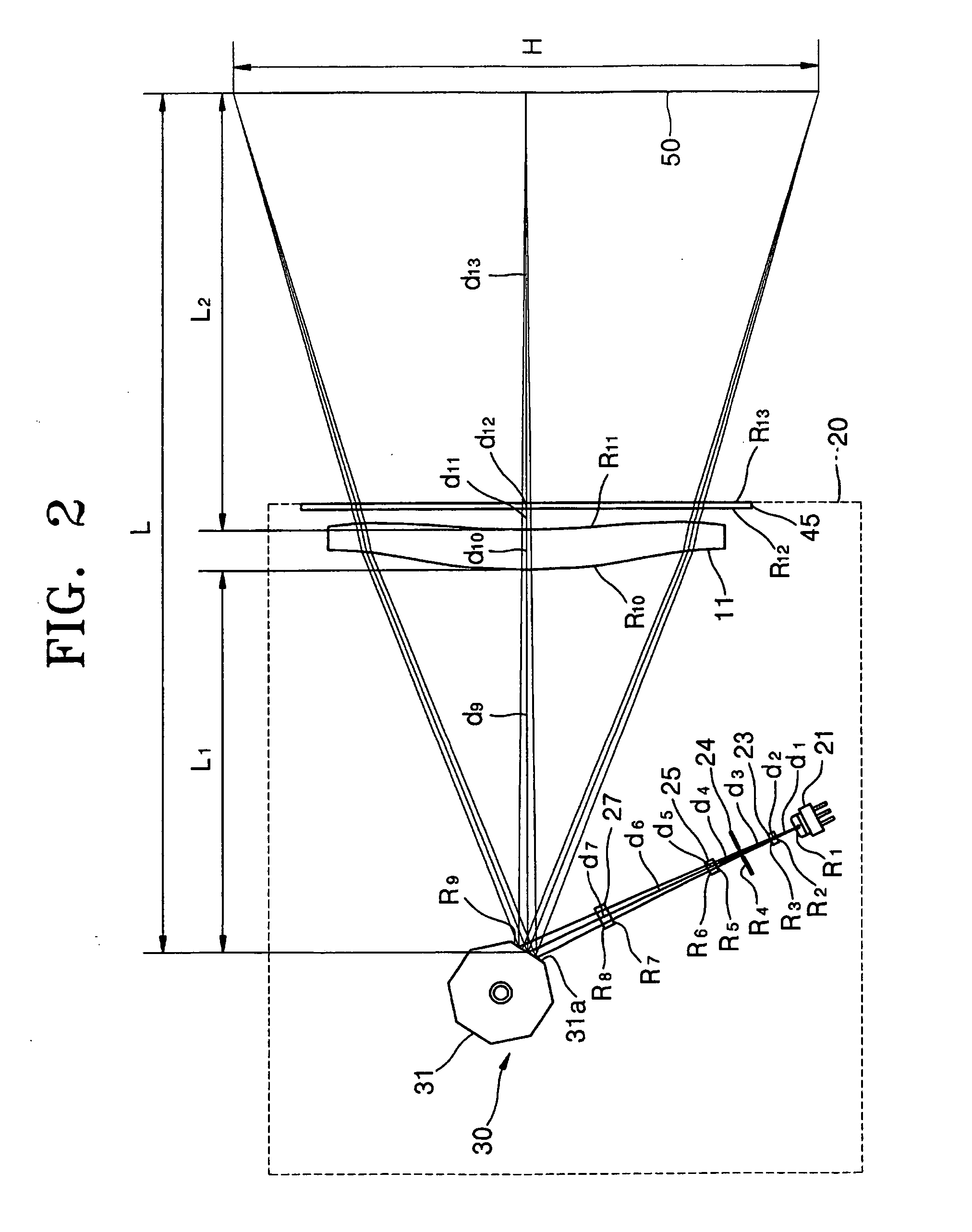
[0023] Referring to FIGS. 2 and 3, an optical scanning unit according to an embodiment of the present invention includes a light source 21 that produces a beam, a beam deflector 30 that deflects and scans the beam emitted by the light source 21, and an f-θ lens 41. The light source 21 optically modulates the beam such that the beam is emitted only onto a portion of the exposed object 50 on which a latent image will be formed. The light source 21 may be constructed as an edge emitting laser diode, a vertical cavity surface emitting laser (VCSEL), or a light-emitting diode (LED). When used for an optical scanning unit structure designed to produce a single scannin...


PUM


Abstract

An optical scanning unit including: a light source which produces and emits a beam; a beam deflector which deflects and scans the beam in a main scanning direction of an exposed object; and an f-θ lens which corrects the beam deflected by the beam deflector at different magnifications for the main scanning direction than for a subscanning direction so that a corrected beam is focused onto the exposed object. When H is an entire length in the main scanning direction of the beam focused onto the exposed object and L is an axial distance between a reflection face of the beam deflector and the exposed object, the relationship of H and L satisfies an expression 0.25≤H2·L≤1.75.

Description

CROSS-REFERENCE TO RELATED APPLICATION [0001] This application claims the priority of Korean Patent Application No. 2003-87986, filed on Dec. 5, 2003, in the Korean Intellectual Property Office, the disclosure of which is incorporated herein by reference. BACKGROUND OF THE INVENTION [0002] 1. Field of the Invention [0003] The present invention relates to an optical scanning unit that scans a beam emitted by a light source onto an exposed object, and more particularly, to an optical scanning unit designed to provide sufficient optical path length between a beam deflector and an exposed object to ease installation of an f-θ lens or f-θ lenses and stable optical performance. [0004] 2. Description of Related Art [0005] Typically, an optical scanning unit is employed in a laser printer, a digital copier, a facsimile, or the like to produce a latent image on an exposed object through main scanning by a beam deflector and subscanning by rotation of the exposed object. [0006] Referring to F...

Claims


Application Information

Patent Timeline
Patent Type & Authority Applications(United States)
IPC IPC(8): G02B26/10G02B13/00G02B13/18
CPCG02B13/0005G02B26/10
Inventor KIM, HYUNG-SOOKIM, HYEONG-CHAE
Owner HEWLETT PACKARD DEV CO LP
Why Eureka
Try Eureka