Image capturing device with duplex scan function and method therefor
- Summary
- Abstract
- Description
- Claims
- Application Information
AI Technical Summary
Benefits of technology
Problems solved by technology
Method used
Image
Examples
first embodiment
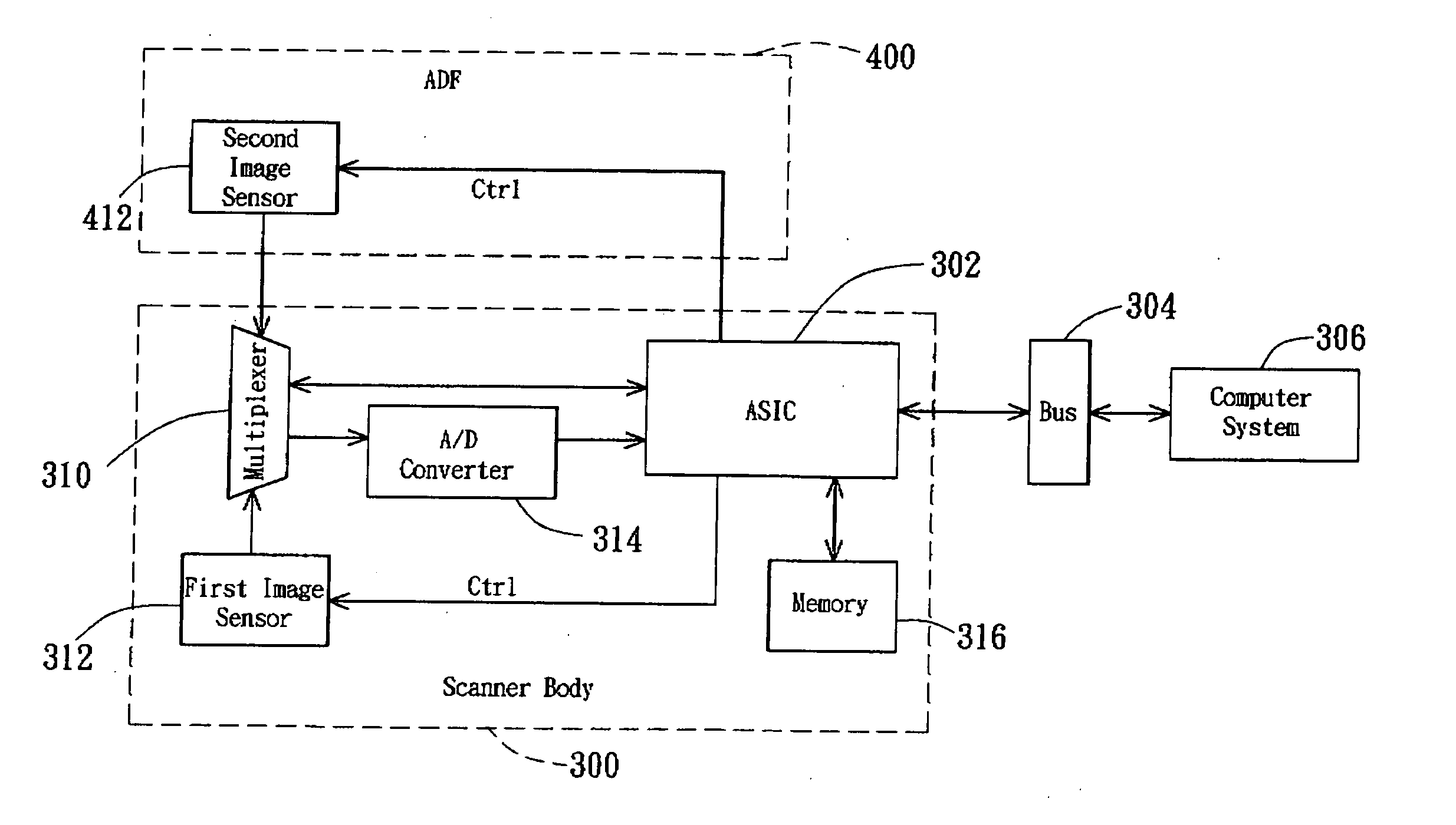
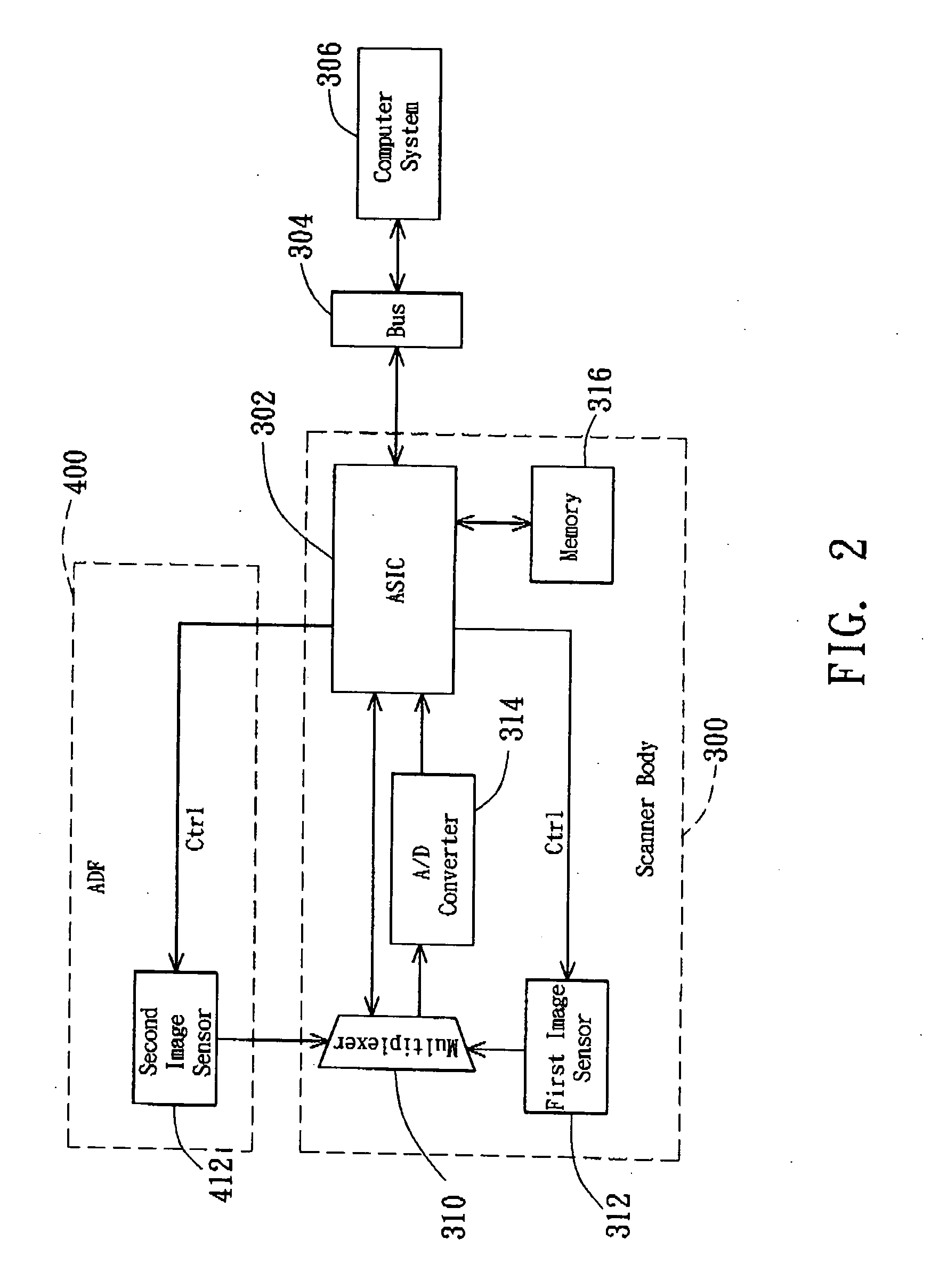
[0023] In the first embodiment, the exposure time (t1) of the sensor of the image capturing device equals twice the shift-out time (s1) of the signal charge, so two signal charges can be shifted out within the exposure time of one optical signal unit. In this case, the first image sensor 312 and the second image sensor 412 respectively sense the first optical signal units and second optical signal units, and enables the first signal charge units and second signal charge units to be continuously, sequentially, and alternately outputted without being temporarily stored in the memory.
[0024]FIG. 4B is a schematic illustration showing an exposure timing control of an image capturing device with duplex scan function according to a second embodiment of the invention. As shown in FIG. 4B, the exposure time (t1) of the sensor of the image capturing device of the second embodiment is longer than twice the shift-out time (s1) of the signal charge, that is, t1>2s1. When the image is being captu...
second embodiment
[0025] In the second embodiment, the exposure time (t1) of the sensor of the image capturing device is longer than the shift-out time (s1) of the signal charges, so two signal charges can be shifted out within the exposure time of one optical signal unit. In this case, the first image sensor 312 and the second image sensor 412 respectively and continuously sense the first optical signal unit and second optical signal, shift out the nth first signal charge A1n at T1=[nt1,nt1+s1], shift out the nth second signal charge B1n at T1=[nt1+s1,nt1+2s1], and do not shift out any signal charge at T1=[nt1+2s1,(n+1)t1]. That is, the (n+1)th first signal charge A1(n+1) cannot be shifted out after the time of t1−2s1 has elapsed.
third embodiment
[0026]FIG. 4C is a schematic illustration showing an exposure timing control of an image capturing device with duplex scan function according to the invention. The exposure time (t2) of the sensor of the image capturing device of the second preferred embodiment is smaller than twice the shift-out time (s2) of the signal charges, that is, t2>2s2. When the image is being captured, the first image sensor 312 and the second image sensor 412 in the first optical module A2 and the second optical module B2 respectively sense the first side data and the second side data of the to-be-scanned document in a disperse manner. The ASIC 302 performs exposure timing controls on the first image sensor 312 and the second image sensor 412 such that the analog signal units of the first side data and the second side data may be sequentially and alternately outputted. First, the first image sensor 312 senses the 1st first optical signal unit of the first side data at T2=0, and then the second image senso...
PUM
 Abstract
Description
Claims
Application Information
 - R&D
- Intellectual Property
- Life Sciences
- Materials
- Tech Scout
- Unparalleled Data Quality
- Higher Quality Content
- 60% Fewer Hallucinations
Browse by: Latest US Patents, China's latest patents, Technical Efficacy Thesaurus, Application Domain, Technology Topic, Popular Technical Reports.
© 2025 PatSnap. All rights reserved.Legal|Privacy policy|Modern Slavery Act Transparency Statement|Sitemap|About US| Contact US: help@patsnap.com


