Method of metallic sandwiched foam composite forming

Inactive Publication Date: 2005-06-23
GM GLOBAL TECH OPERATIONS LLC
View PDF15 Cites 10 Cited by
  • Summary
  • Abstract
  • Description
  • Claims
  • Application Information

AI Technical Summary

Benefits of technology

[0010] The invention provides a basis for producing complex, tough, and “stiff” structures via an essentially single economic forming operation with commensurate benefits in providing low weight composites. Further areas of applicability of the present invention will become apparent from

Problems solved by technology

Formation of such structures to date has not been feasible due to the cost of formation of the foam portion which needs to be shaped prior to the attac

Method used


Image

  • Method of metallic sandwiched foam composite forming
  • Method of metallic sandwiched foam composite forming
  • Method of metallic sandwiched foam composite forming

Examples


Embodiment Construction

[0017] The following description of the preferred embodiments is merely exemplary in nature and is in no way intended to limit the invention, its application, or uses.

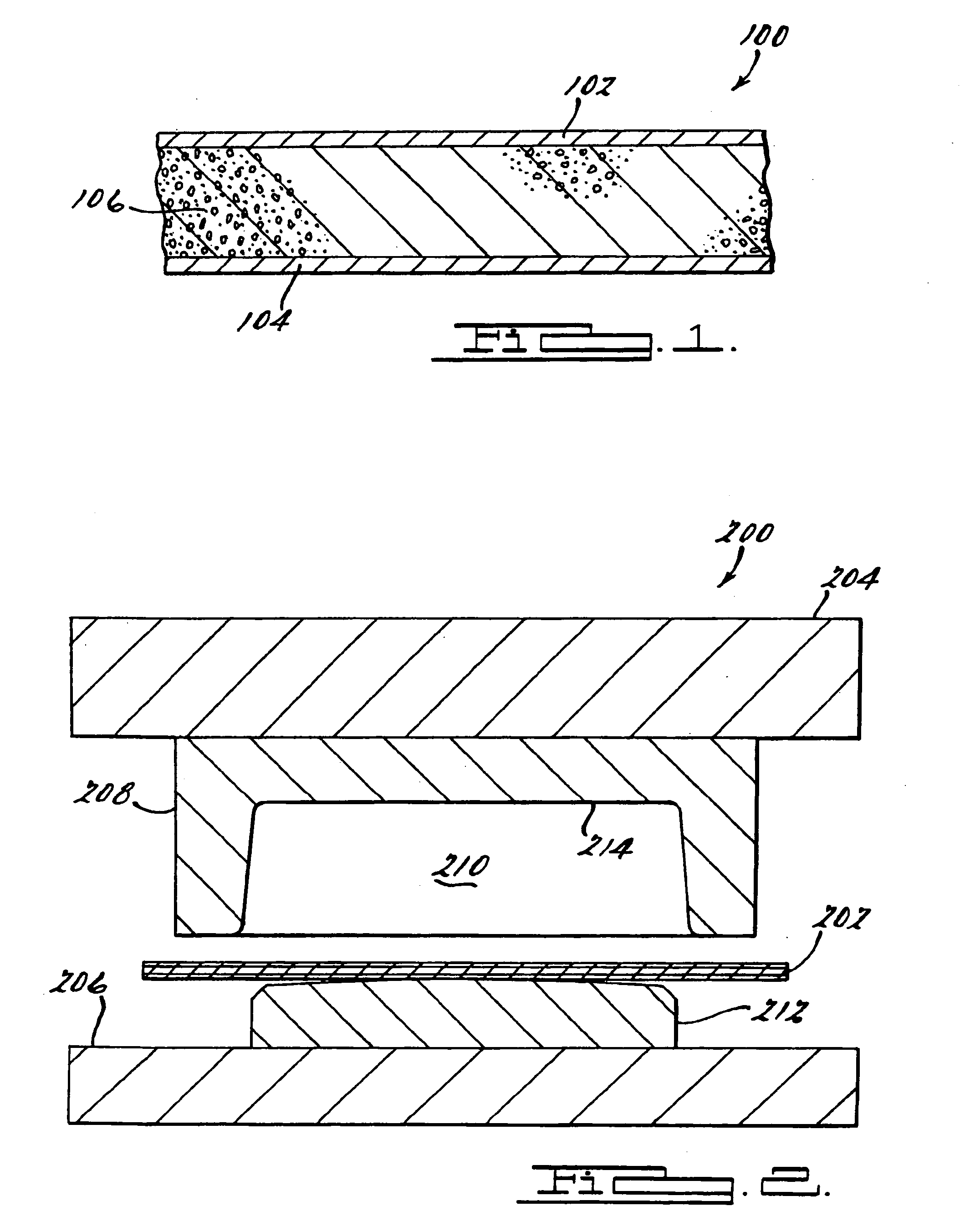
[0018] The preferred embodiments involve using superplastic (SPF) or quickplastic (QPF) (“quick plastic” or “super plastic”) forming technology approaches in forming a metallic composite structure. In this regard, a planar metal sheet capable of quick-plastic formation is used in the SPF or QPF procedure. During the SPF or QPF process, the temperature of the planar metal sheet is increased so that it is between the super plastic forming temperature and the melting temperature. The sheet metal 102 is deformed using SPF or QPF procedures to form a three dimensional formed metal sheet. The formation of the composite structure occurs either during or after the SPF or QPF of the sheet metal. In this regard, the formation of the metallic composite occurs when a metallic foam layer 106 is coupled to the formed metallic sheet...


PUM

PropertyMeasurementUnit
Lengthaaaaaaaaaa
Temperatureaaaaaaaaaa
Pressureaaaaaaaaaa

Abstract

Disclosed is a method of forming metallic composite structures The method utilizes superplastic and quickplastic formation methodologies in conjunction with the use of appended engineered metallic foams to provide a energy absorbing materials.

Description

FIELD OF THE INVENTION [0001] The present invention relates to a method of making metallic composite structures and more specifically, a method for forming metallic composite panels having an interior metallic foam core. BACKGROUND OF THE INVENTION [0002] A useful method for metal sheet forming is provided in “quickplastic” or “superplastic” (“quick plastic” or “super plastic”) forming approaches (QPF or SPF) in which sheet metal is formed into a complex shape in a single-sided forming tool using gas pressure to provide the forming force to transform the sheet metal into a form. In this regard, metal sheets such as aluminum are heated and then formed into shapes using gas pressure. The technology allows complex shapes to be formed from materials otherwise difficult to form to the complex shape. Details in these methods are presented in commonly assigned U.S. Pat. No. 5,974,847 for a “Superplastic Forming Process” issued to Fredrick I. Saunders, et al., on Nov. 2, 1999, and U.S. Pat....

Claims


Application Information

Patent Timeline
IPC IPC(8): B23K1/19B23P11/00B23P25/00B32B5/18
CPCB23K1/19B23K2201/02B23K2201/18B23K2201/22Y10T29/49906Y10T29/49805Y10T29/49885Y10T29/49908Y10T428/12479Y10T29/49924B23K2101/02B23K2101/18B23K2101/22
Inventor MORALES, ARIANNA T.KRAJEWSKI, PAUL E.
Owner GM GLOBAL TECH OPERATIONS LLC
Why Eureka
Try Eureka