
Tissue surface treatment apparatus and method

a tissue surface treatment and tissue technology, applied in the field of tissue surface treatment apparatus and method, can solve the problems of compromising the function of the target organ, metastasis and spread of disease, surgeons may be forced to remove or injure healthy tissue, etc., and achieve the effect of less curvatur

Inactive Publication Date: 2005-06-23
ANGIODYNAMICS INC
View PDF37 Cites 160 Cited by
  • Summary
  • Abstract
  • Description
  • Claims
  • Application Information

AI Technical Summary

Benefits of technology

[0011] In still another embodiment, the surface treatment apparatus includes a first RF electrode, a second RF electrode and a third RF electrode. Each of the first, second and third RF electrodes have a tissue piercing distal end and are positi...

Problems solved by technology

In an effort to fully remove or resect the tumor, the surgeon may be forced to remove or injure healthy tissue, compromising the function of the target organ.
Further, the surgeon must exercise care in not cutting the tumor in a manner that creates seeding of the tumor, resulting in metastasis and spread of the disease.
However, these therapies in their present form have several critical drawbacks including: (i) inability to ablate / necrose the entire tumor; (ii) inability to ablate or necrose tissue along the entire length / perimeter of the tumor margin; (iii) inability to reduce lesion size sufficiently to reduce pain levels; (iv) inability to treat smaller tumors without potentially damaging surrounding healthy tissue and / or critical organs and structures; (v) inability of introducer to deploy device at an angle or otherwise access difficult to reach tumors; and (vi) inability to determine a meaningful clinical endpoint.
In particular tumors lying near or underneath an organ surface present a distinct set of problems to current ablative therapies.

Method used


Image

  • Tissue surface treatment apparatus and method
  • Tissue surface treatment apparatus and method
  • Tissue surface treatment apparatus and method

Examples


Embodiment Construction

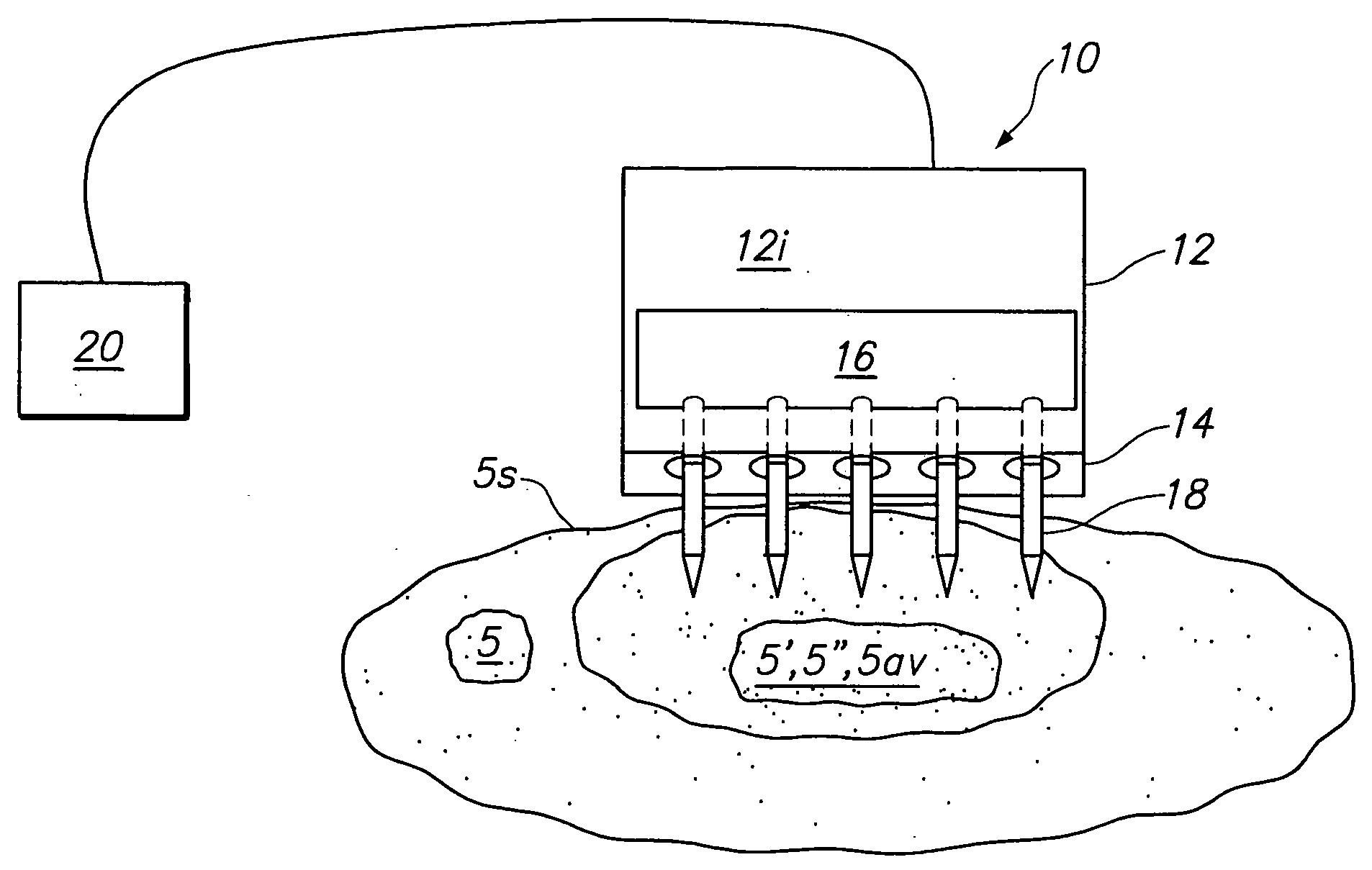
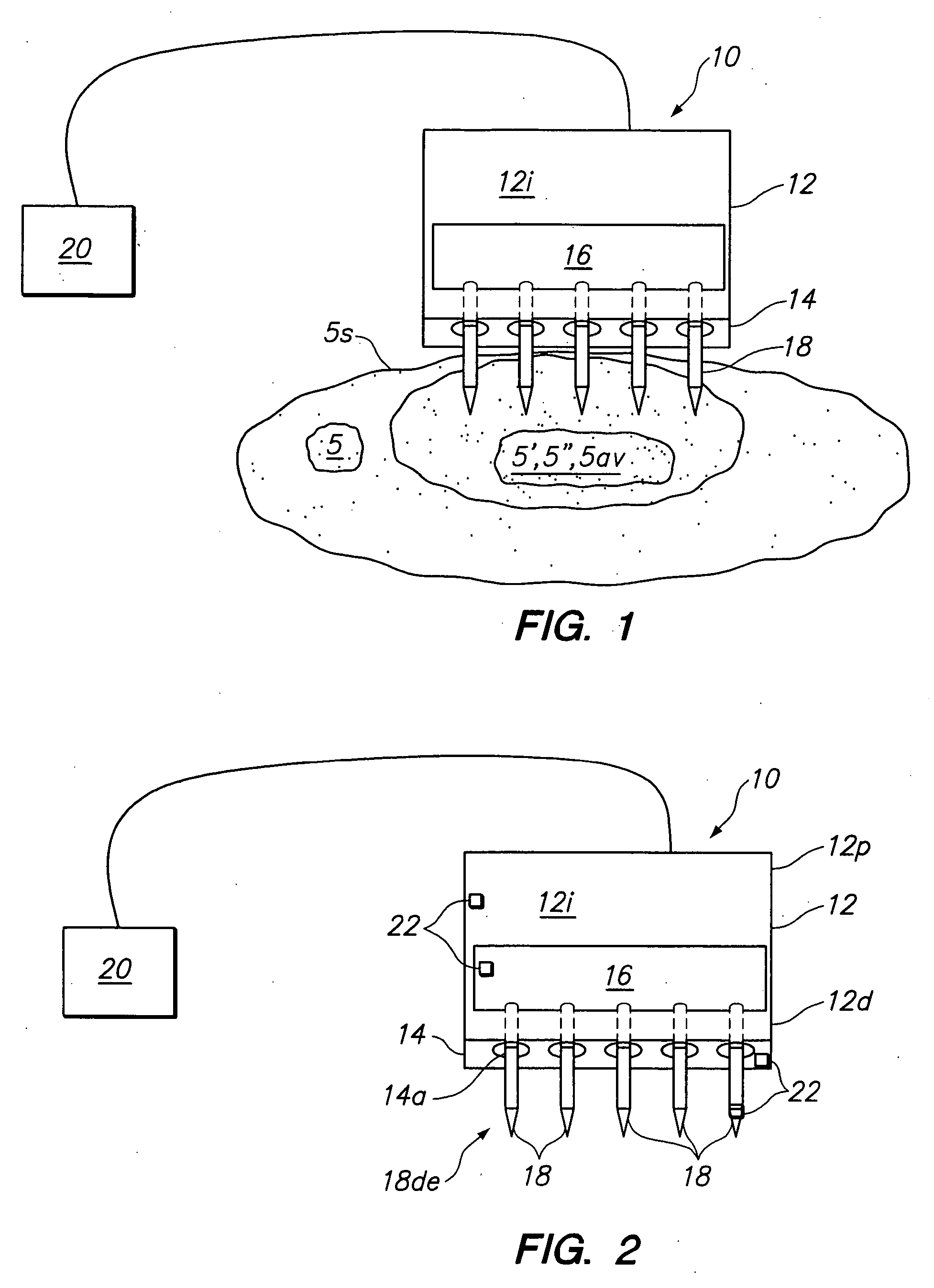
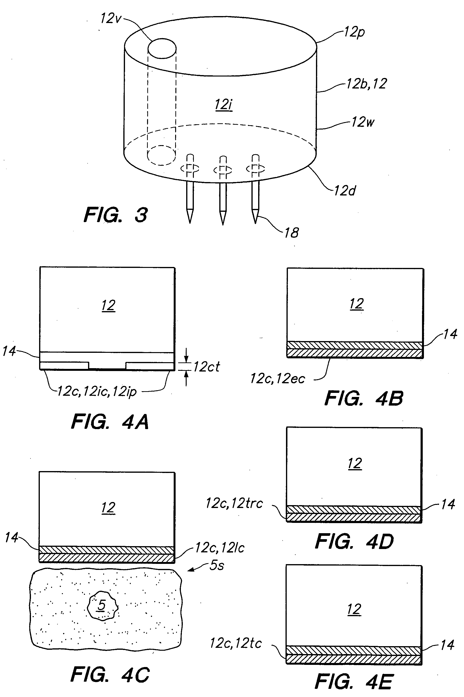
[0078] In order to superficially treat organ tumors (e.g. hepatic tumors), particularly those near the tissue surface it is desirable for the physician to be able to deploy electrodes into the tumor while avoiding and minimizing injury to adjacent critical anatomical structures that are adjacent and underneath the target tumor mass.

[0079] The present invention provides an apparatus and method to address this and other need in performing surface treatment of tissue masses and tumors such as liver tumors using both open chest procedures and minimally invasive procedures. In particular, embodiments of the invention are configured to selectively deploy individual electrodes or an array of electrodes into a tumor or tissue mass so as to achieve a particular pattern to precisely treat the tumor while avoiding adjacent critical anatomical structures such as vasculature (e.g. hepatic veins) and nerve plexi. Further, the apparatus of the present invention allows the electrodes to be deploye...


PUM


Abstract

A tissue surface treatment apparatus includes a housing having a proximal end, a distal end including a tissue contacting surface, an interior defined by the housing and a handpiece coupled to the housing. The contactinc surface has a plurality of apertures. An energy delivery device including an electrode is positionable in the housing interior. The electrode includes a tissue penetrating distal end in substantial alignment with an aperture. The electrode is configured to be advanced from the housing interior through the aperture and into a target tissue site to define an ablation volume at least partly bounded by a tissue surface. An advancement device is coupled to the energy delivery device and is at least partly positionable within at least one of the housing or the handpiece. The advancement device is configured to advance the electrode from the housing interior into the target tissue site and withdrawal the electrode into the housing interior. A cable is coupled to the housing or the energy delivery device and is configured to be coupled to an energy source.

Description

BACKGROUND OF THE INVENTION [0001] 1. Field of the Invention [0002] This invention relates generally to an apparatus and method for the minimally invasive treatment and ablation of tissue masses such as tumors, and more particularly to a tissue surface treatment apparatus with independently deployable electrodes configured to controllably ablate a tumor proximate or beneath a tissue surface. [0003] 2. Description of the Related Art [0004] Standard surgical procedure, such as resection, for treating benign and malignant tumors of the liver and other organs have several key shortcomings affecting efficacy, morbidity and mortality. In an effort to fully remove or resect the tumor, the surgeon may be forced to remove or injure healthy tissue, compromising the function of the target organ. Further, the surgeon must exercise care in not cutting the tumor in a manner that creates seeding of the tumor, resulting in metastasis and spread of the disease. Also surgical resection procedures are...

Claims


Application Information

Patent Timeline
IPC IPC(8): A61B18/14
CPCA61B18/1477A61B2018/00011A61B2018/00017A61B2018/00029A61M2025/0085A61B2018/143A61B2018/1475A61M25/1002A61B2018/00291
Inventor MORRIS, DAVID L.DANIEL, STEVEN A.BALBIERZ, DANIEL J.
Owner ANGIODYNAMICS INC
Learn More