Method and system for sliding mode control of a turbocharger

a technology of sliding mode and turbocharger, which is applied in the direction of electric control, machines/engines, instruments, etc., can solve the problems of complex control of turbochargers, increased air mass, and increased power and torque, and achieve the effect of minimizing square errors

Active Publication Date: 2005-06-23
GARRETT TRANSPORATION I INC
View PDF11 Cites 41 Cited by
  • Summary
  • Abstract
  • Description
  • Claims
  • Application Information

AI Technical Summary

Benefits of technology

[0014] According to another aspect of the invention, the system parameters are identified according to coefficients of linear transfer functions that model the response of the turbocharger at an operating state. The coefficients may include any of pulsation, damping, and gain. These linear transfer function models of the turbocharger may be of at least a second order, however, some turbocharger systems may be modeled at higher orders. The identification of these system parameters may be determined by an optimization equation. For example, one advantageous optimization equation minimizes the square error between the measured boost pressure and the simulated or modeled boost pressure.

Problems solved by technology

The increase of the mass of air creates more power and torque when the piston is forced downward by the resulting explosion.
The control of a turbocharger is complicated by the inherent lag in the engine exhaust system and the transient response times of the mechanical elements of the variable-geometry mechanism.
On the other hand, a variation in the VNT position affects both boost pressure and engine back pressure, which ultimately changes EGR flow.
However, these approaches require extensive calibration to determine proper PID gains at many different engine states.

Method used


Image

  • Method and system for sliding mode control of a turbocharger
  • Method and system for sliding mode control of a turbocharger
  • Method and system for sliding mode control of a turbocharger

Examples


Embodiment Construction

[0027] The present inventions now will be described more fully hereinafter with reference to the accompanying drawings, in which some, but not all embodiments of the inventions are shown. Indeed, these inventions may be embodied in many different forms and should not be construed as limited to the embodiments set forth herein; rather, these embodiments are provided so that this disclosure will satisfy applicable legal requirements. Like numbers refer to like elements throughout.

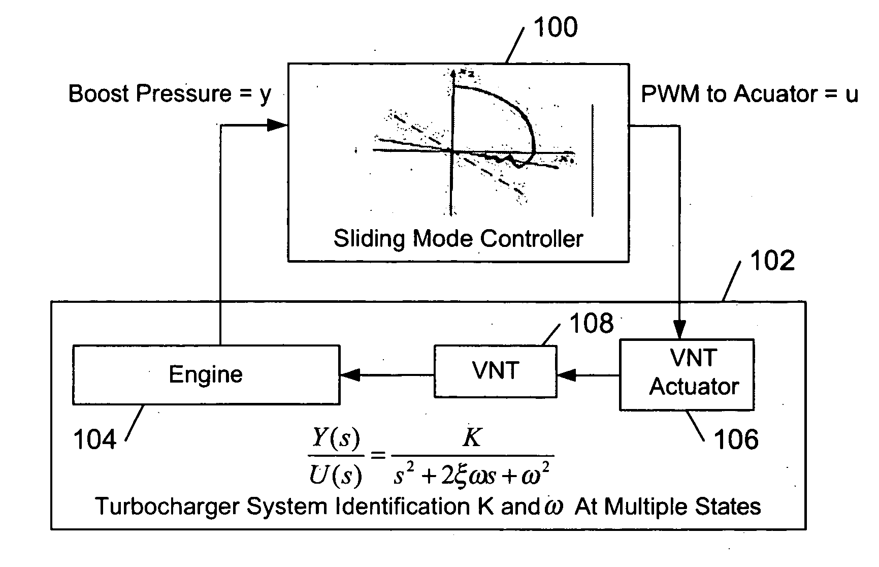
[0028]FIG. 1 illustrates a sliding mode control system including a sliding mode controller 100 and turbocharged internal combustion engine system 102 according to one embodiment of this invention. The engine system comprises an internal combustion engine 104, a VNT actuator 106, and a VNT 108 in air and exhaust flow communication with the engine. The VNT 108 is a variable-geometry member in the form of a number of aerodynamic vanes that are movably attached to an inlet nozzle of the VNT turbine. An example V...


PUM


Abstract

A method for defining a sliding mode control system for a turbocharger system is provided. The method includes perturbing a turbocharger actuator and measuring turbocharger boost pressure output from the perturbation. The perturbation and measurements are repeated for a plurality of states of operation of the turbocharger. System parameters identified for each of the plurality of states from the plurality of perturbations and measurements. A sliding mode control law may be defined for each of the plurality of states from the system parameters. A sliding mode control system for controlling the boost pressure of a turbocharger is also provided. An actuator for controlling the boost pressure is electrically controlled by a sliding mode controller to stabilize the turbocharger system toward a setpoint on a sliding surface. The control law is determined from a plurality of linear models from a plurality of operating states of the turbocharger system.

Description

FIELD OF THE INVENTION [0001] The present invention relates to turbochargers and turbocharger controllers and methods, and more particularly to turbocharger controllers and methods incorporating sliding mode control for non-linear control applications. BACKGROUND OF THE INVENTION [0002] A turbocharger improves the efficiency of an internal combustion engine by increasing the pressure and density of the intake air. At the outlet of the engine, an engine's exhaust gases are directed to a turbine wheel translating exhaust energy into rotational mechanical energy of a shaft. The shaft couples the turbine to a compressor disposed in the intake flow of the engine. The compressor increases the pressure and density of the intake flow so that the air-fuel mixture is more combustible. The increase of the mass of air creates more power and torque when the piston is forced downward by the resulting explosion. This process results in a boost to overall engine power. [0003] Turbochargers are requ...

Claims


Application Information

Patent Timeline
Patent Type & Authority Applications(United States)
IPC IPC(8): F02D41/00F02D41/14
CPCF02D41/0007Y02T10/144F02D2041/1423F02D41/1403Y02T10/12
Inventor KOLAVENNU, SOUMITRI N.BARTHELET, PIERRE
Owner GARRETT TRANSPORATION I INC
Why Eureka
Try Eureka