Method for automatically calibrating the frequency range of a PLL and associated PLL capable of automatic calibration
a technology of automatic calibration and frequency range, applied in the field of phase locked loops (plls), can solve the problem of adding to the cost of manufacturing the pll
- Summary
- Abstract
- Description
- Claims
- Application Information
AI Technical Summary
Benefits of technology
Problems solved by technology
Method used
Image
Examples
first embodiment
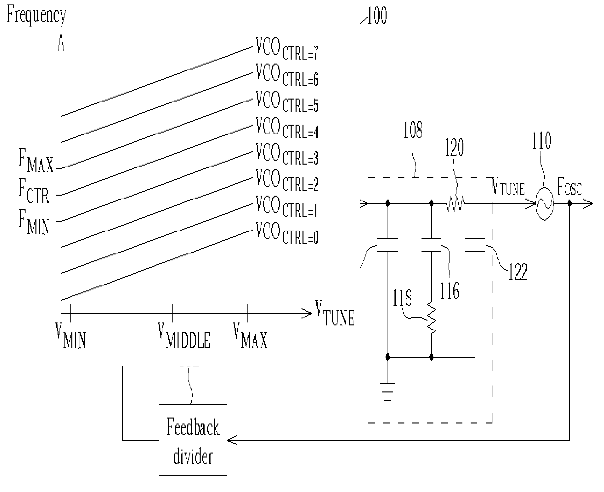
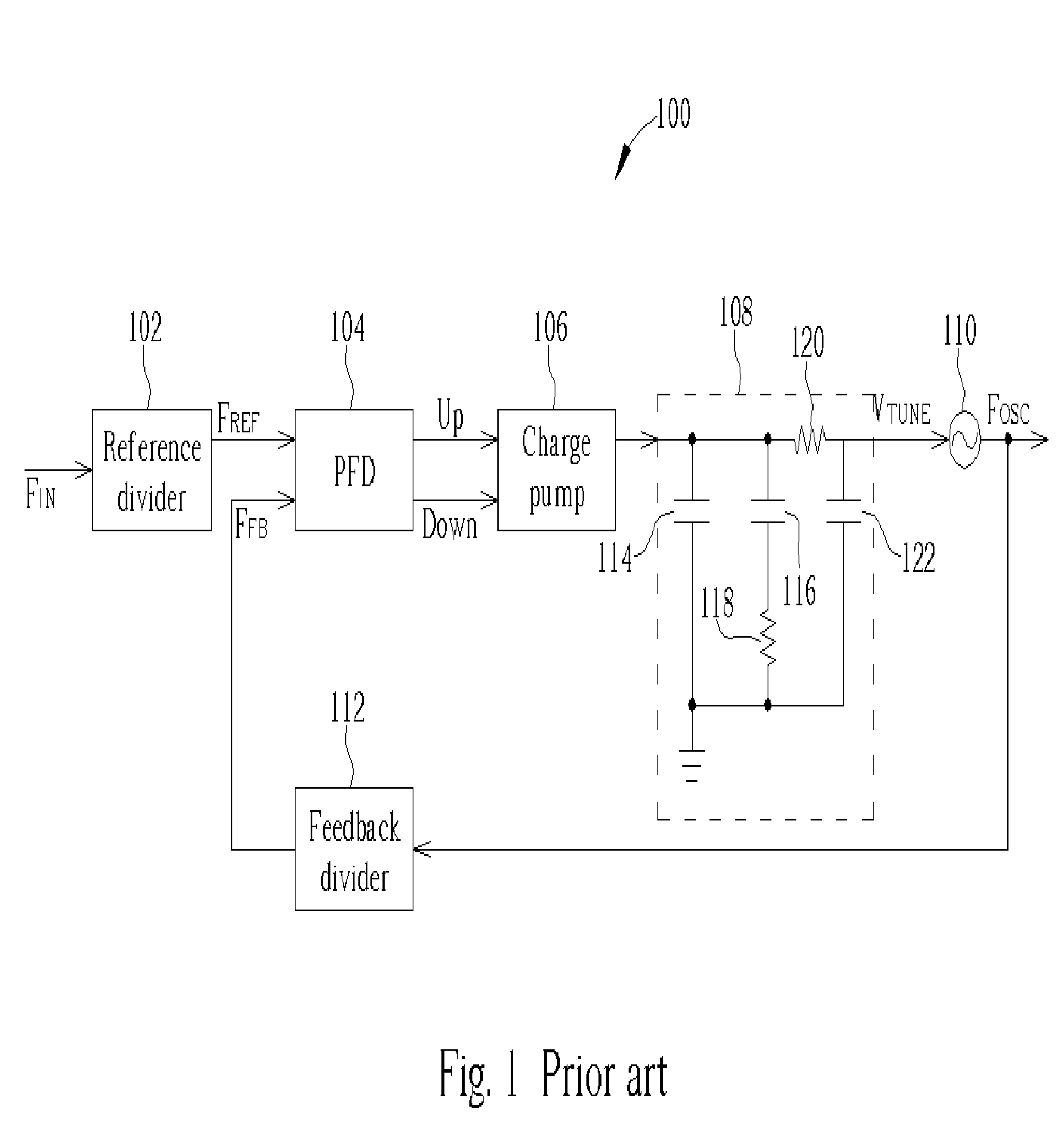
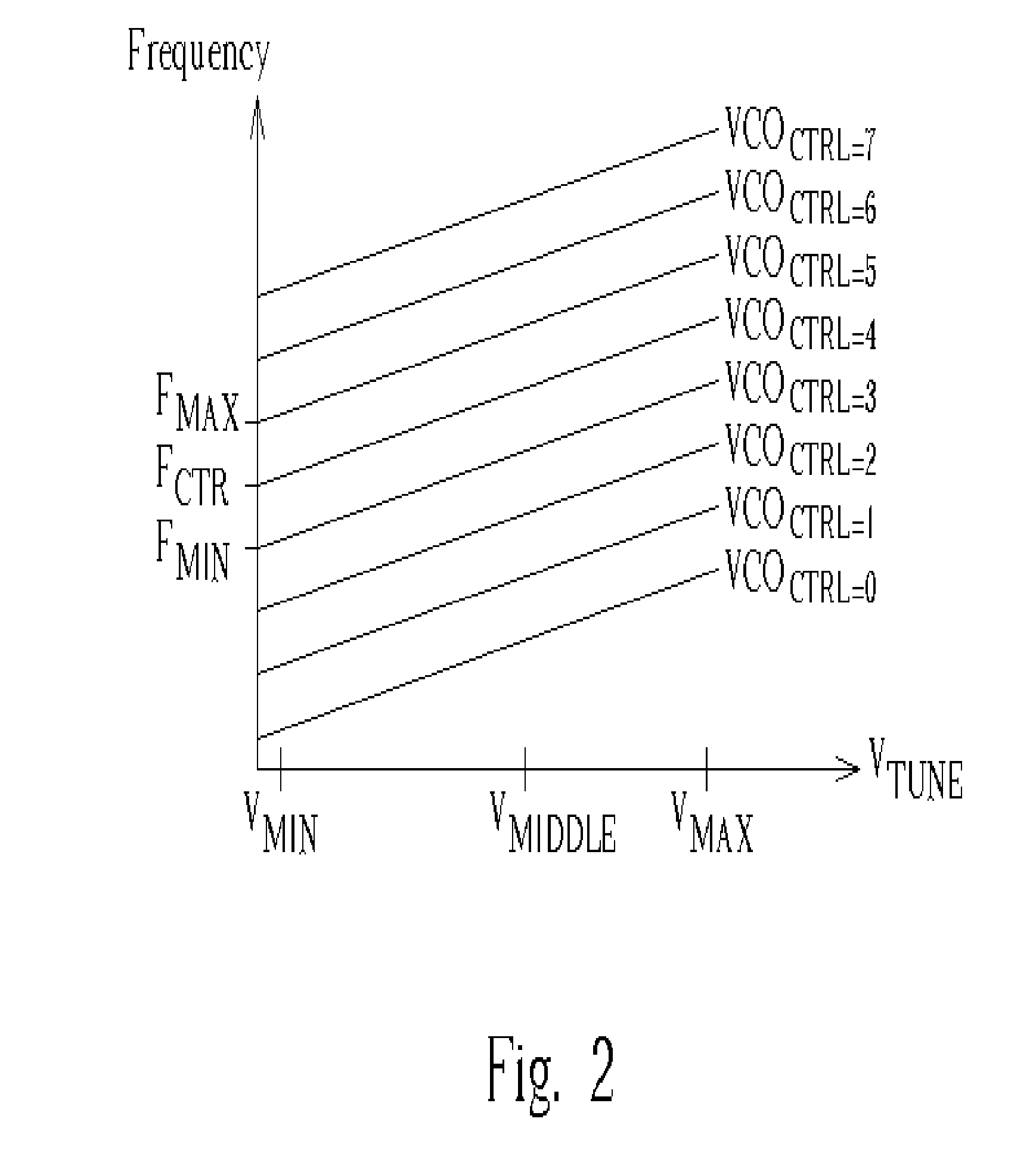
[0030]FIG. 3 shows a block diagram a PLL 300 capable of automatic calibration according to the present invention. The PLL 300 includes a reference divider 302, a phase / frequency detector (PFD) 304, a charge pump 306, a switch 308, a loop filter 310, a pre-charge unit 311, a voltage controlled oscillator 312, a feedback divider 314, a frequency detector 316, a VCO controller 318, and a loop controller 320. During normal PLL operations, the switch 308 connects the output of the charge pump 306 to the loop filter 310 and the operation of the reference divider 302, the PDF 304, the charge pump 306, the loop filter 310, the VCO 312, and the feedback divider 314 is the same as explained for FIG. 1. However, unlike the conventional PLL described in FIG. 1, when the PLL 300 is switched on, it uses a linear search to automatically calibrate the VCO frequency range, preventing the need to hardwire the frequency range during manufacturing, accounting for process variations, and allowing the PL...
second embodiment
[0046] In the present invention, when starting the automatic calibration process, the pre-charge unit 702 charges the loop filter to a middle voltage value and the VCO controller 708 sets the VCO to the middle frequency range and initializes an iteration counter j to 1. The frequency detector 706 compares the reference signal FREF with the feedback signal FFB. If the second rising edge of the reference signal FREF leads the second rising edge of feedback signal FFB, then the frequency detector 316 asserts “Shift Up” for the time duration between the two edges. When the VCO controller 318 receives the “Shift Up” signal, this means the feedback signal is too slow and the VCO controller 318 increases the VCO frequency range by (number of ranges) / 2j+1, where j represents the iteration count. Alternatively, if the second rising edge of the reference signal FREF lags the second rising edge of feedback signal FFB, then the frequency 316 asserts “Shift Down” for the time duration between th...
PUM
 Abstract
Description
Claims
Application Information
 - R&D
- Intellectual Property
- Life Sciences
- Materials
- Tech Scout
- Unparalleled Data Quality
- Higher Quality Content
- 60% Fewer Hallucinations
Browse by: Latest US Patents, China's latest patents, Technical Efficacy Thesaurus, Application Domain, Technology Topic, Popular Technical Reports.
© 2025 PatSnap. All rights reserved.Legal|Privacy policy|Modern Slavery Act Transparency Statement|Sitemap|About US| Contact US: help@patsnap.com


