Radio IC tag, method for manufacturing radio IC tag, and apparatus for manufacturing radio IC tag

a radio ic tag and radio ic technology, applied in the direction of electrical apparatus casings/cabinets/drawers, instruments, burglar alarm mechanical actuation, etc., can solve the problems of weak radio wave intensity for radio ic tags to transmit, short detectable distance, and still holding

Inactive Publication Date: 2005-06-30
HITACHI LTD
View PDF4 Cites 152 Cited by
  • Summary
  • Abstract
  • Description
  • Claims
  • Application Information

AI Technical Summary

Benefits of technology

[0010] It is therefore an object of the present invention to provide a radio IC tag which can be made thin and can have a long communication distance, a method for manufacturing the radio IC tag, and an apparatus for manufacturing the radio IC tag.

Problems solved by technology

However, the aforementioned radio tag has a problem that, when the tag is bonded to a metallic article as an example, it becomes impossible to neglect the fact that radio wave received by the radio tag is absorbed into the metallic article, which results in that the intensity of radio wave for the radio tag to transmit becomes weak and thus its detectable distance becomes short.
This problem still holds true even for a radio IC tag which is a combination of an IC chip and the radio tag added thereto.
As a result, it becomes impossible to obtain a sufficient operating power and therefore impossible also to read out the information and transmit the information to the place located away by a necessary distance.
However, the thicker spacer for obtaining the longer communication distance results in the increased size of the radio IC tag.
This involves disadvantages including its limited application field.
When such a radio IC tag is actually used, the tag also may be hit by persons or objects and be peeled off.
In this way, such a tag has a poor usability.

Method used


Image

  • Radio IC tag, method for manufacturing radio IC tag, and apparatus for manufacturing radio IC tag
  • Radio IC tag, method for manufacturing radio IC tag, and apparatus for manufacturing radio IC tag
  • Radio IC tag, method for manufacturing radio IC tag, and apparatus for manufacturing radio IC tag

Examples


Embodiment Construction

[0020] The invention will be detailed in connection with preferred embodiments of the invention with reference to the accompanying drawings.

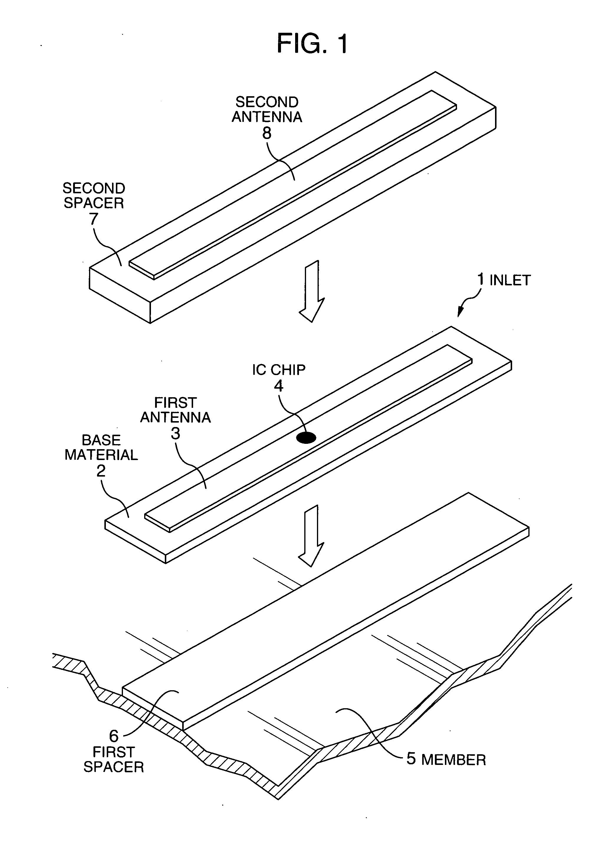
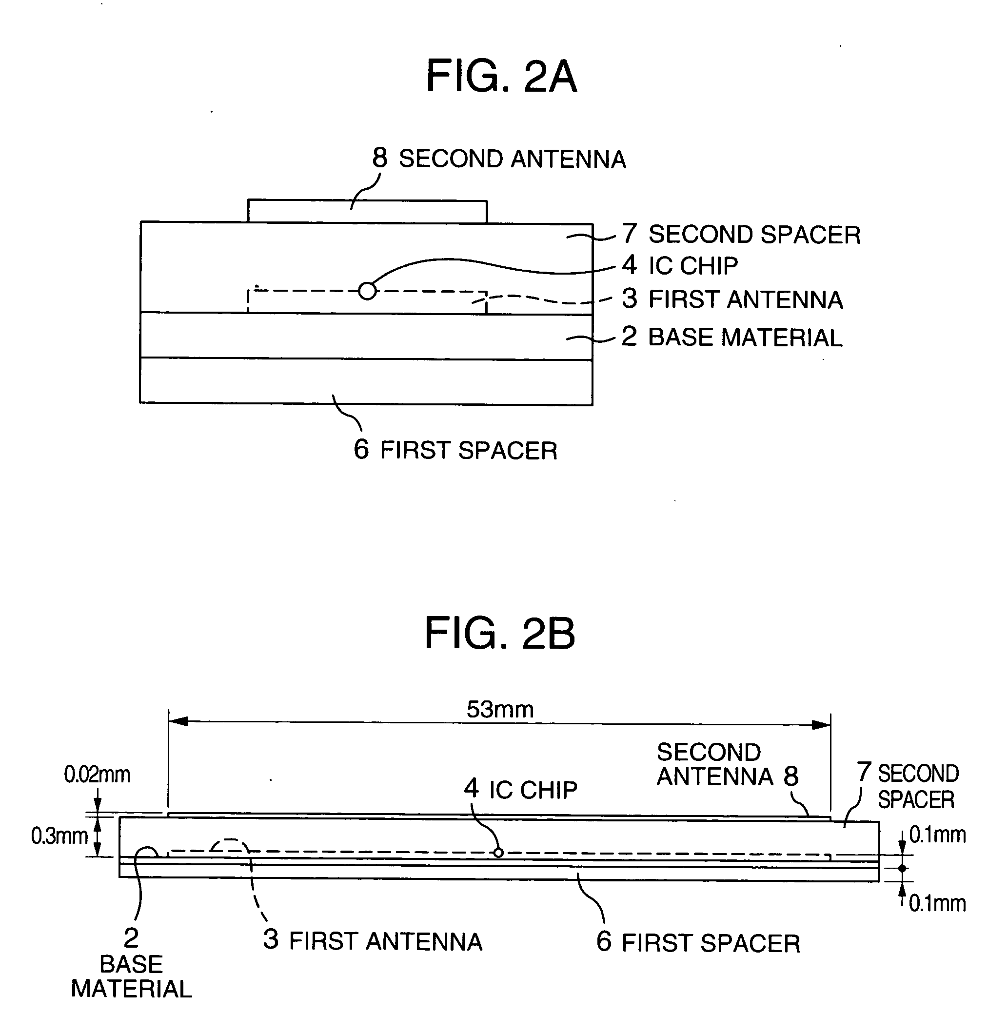
[0021]FIG. 1 shows a structure of a radio IC tag in accordance with a first embodiment of the present invention. FIG. 2A is a cross-sectional view of the radio IC tag shown in FIG. 1 taken along a width direction, and FIG. 2B is a cross-sectional view of the radio IC tag shown in FIG. 1 taken along a longitudinal direction. A plate-shaped assembly in the radio IC tag of FIG. 1, which includes a base material 2, an antenna (first antenna) 3, and an IC chip 4, is generally referred to as an inlet 1. The radio IC tag is mounted on a member 5.

[0022] The radio IC tag of the present embodiment, as shown in FIG. 1, includes the inlet 1, a first spacer 6 mounted on the lower side (e.g., on its one side having the metallic member 5 ) of the inlet 1, a second spacer 7 mounted on the upper side (e.g., on the other side opposed to the member 5 ) of the in...


PUM

PropertyMeasurementUnit
thicknessaaaaaaaaaa
thicknessaaaaaaaaaa
thicknessaaaaaaaaaa

Abstract

A radio IC tag includes a first antenna and a first spacer, and is arranged so as to generate an operating power by a radio wave received at the first antenna and having a predetermined frequency, operate an IC chip using the power, read out identification information stored in the IC chip, and transmits the identification information, further includes a second antenna having a predetermined length for resonating with the radio wave having the predetermined frequency, and a second spacer provided between the first antenna and the second antenna for holding a distance between the both antennas.

Description

BACKGROUND OF THE INVENTION [0001] 1. Field of the Invention [0002] The present invention relates to a radio IC tag which can be suitably mounted to a member having a large dielectric constant, a method for manufacturing the radio IC tag, and an apparatus for manufacturing the radio IC tag. [0003] 2. Description of the Related Art [0004] For purposes of preventing an article itself and the article management from theft and also preventing the article from falsification, a radio tag for acquiring article information from an article in a non-contact manner has been developed and is proceeding toward practical utilization. For example, JP-A-11-339142 discloses a resonance circuit including a conductor as an antenna and an insulating-based material sheet used as a spacer, both used for a conventional radio tag for a purpose of preventing an article from theft. Accordingly, a radio wave having a predetermined frequency is transmitted to the radio tag (a tag for preventing an article from...

Claims


Application Information

Patent Timeline
Patent Type & Authority Applications(United States)
IPC IPC(8): G08B13/24
CPCG06K19/07749G06K19/07767G06K19/07771G08B13/2414Y10T29/49117G08B13/2437G08B13/2445H01B17/34G08B13/2417
Inventor SAKAMA, ISAOASHIZAWA, MINORU
Owner HITACHI LTD
Why Eureka
Try Eureka