
Cooling system for a vehicle and a vehicle comprising the cooling system

Inactive Publication Date: 2005-06-30
VOLVO CONSTR EQUIP
View PDF4 Cites 9 Cited by
  • Summary
  • Abstract
  • Description
  • Claims
  • Application Information

AI Technical Summary

Benefits of technology

[0004] According to a previously known system the coupling means consists of a thermostat, which is operatively controlled by the engine temperature to cut in automatically when the engine temperature exceeds a certain value.
[0005] According to this previously known system just one pump is used to provide cooling both for the vehicle engine and for the hydraulic components of the vehicle. One problem with this system is that under certain conditions the thermostat will not cut in, with the result that the hydraulic components do not receive the necessary cooling. One example of this occurs in an extremely cold climate when the vehicle is used in such a way that its hydr

Problems solved by technology

One problem with this system is that under certain conditions the thermostat will not cut in, with the result that the hydraulic components do not receive the necessary cooling.
One example of this occurs in an extremely cold climate when the vehicle is used in such a way that its hydraulic components become so hot that cooling is required, whilst the engine is not hot enough for the thermostat to cut in.
A problem with this system is that under certain operating conditions the thermostat will not cut in, with the result that the transmission components do not receive the necessary cooling.
A further problem with the previously known system is that if the thermostat fails and does not or is not open, there is no cooling at all of the hydraulic or transmission components.
Owing to the ever more stringent requirements governing vehicle exhaust emissions, this temperature limit is also increasing.

Method used


Image

  • Cooling system for a vehicle and a vehicle comprising the cooling system
  • Cooling system for a vehicle and a vehicle comprising the cooling system
  • Cooling system for a vehicle and a vehicle comprising the cooling system

Examples


Embodiment Construction

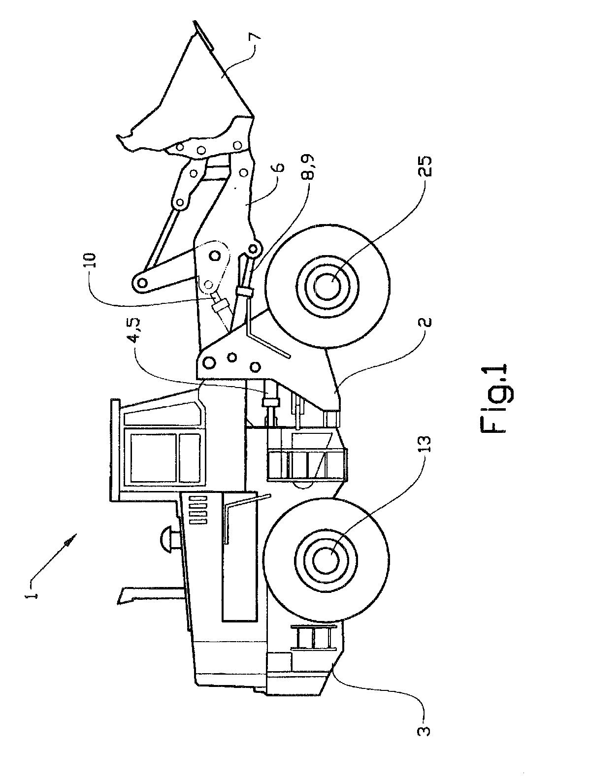
[0017]FIG. 1 shows a wheel loader 1. The body of the wheel loader 1 comprises a front body part 2 and a rear body part 3, these parts being joined to one another by an articulated connection. The body parts 2,3 can be rotated in relation to one another about an articulated joint by means of two hydraulic components in the form of working cylinders 4,5 arranged between the two parts.

[0018] The working cylinders 4,5 are therefore designed for turning the wheel loader 1.

[0019] The wheel loader 1 furthermore has a load unit 6 and an implement in the form of a shovel 7 arranged on the load unit. The load unit 6 can be raised and lowered in relation to the front part 2 of the vehicle by means of two hydraulic components in the form of two working cylinders 8,9, each of which is connected at one end to the front part of the vehicle 2 and at its other end to the load unit 6. The shovel 7 can be tilted in relation to the load unit 6 by means of a further hydraulic component in the form of ...


PUM


Abstract

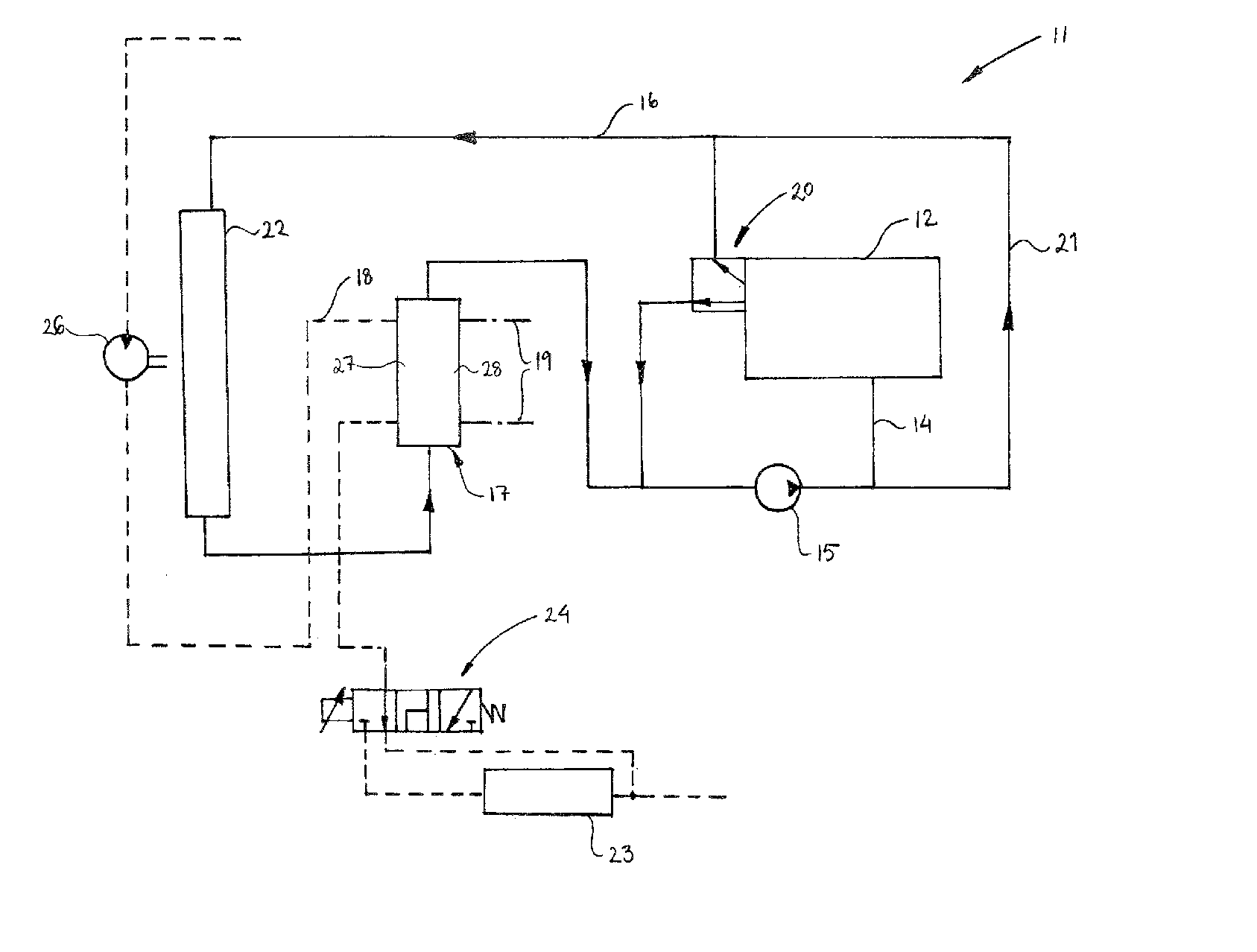
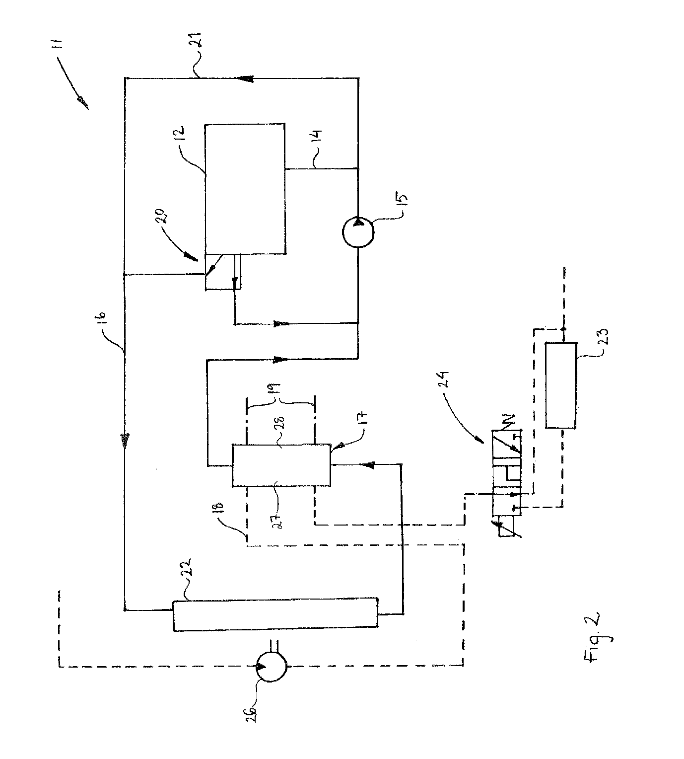
A cooling system for a vehicle includes a first cooling circuit coupled to the vehicle engine for cooling the latter and a pump arranged in the first cooling circuit for pumping a coolant to the engine. The system further includes a second cooling circuit for cooling at least one other component in the vehicle, and an arrangement for coupling the second cooling circuit into the first cooling circuit in order to also supply the second cooling circuit with coolant from the pump. The cooling system further includes a line coupled from the first cooling circuit to the second cooling circuit bypassing the coupling means so that the second cooling circuit is supplied with coolant from the pump via the bypass line even when the coupling means is set to the disconnected position.

Description

[0001] This application is a continuation of PCT / SE2003 / 001158, filed Jul. 2, 2003, and claims priority to SE 0202724-1, filed Sep. 13, 2002, both of which are incorporated by reference.BACKGROUND AND SUMMARY [0002] The present invention relates to a cooling system for a vehicle, the system comprising a first cooling circuit coupled to the vehicle engine for cooling the latter, a pump arranged in the first cooling circuit for pumping a coolant to the engine, a second cooling circuit for cooling at least one other component in the vehicle, and means of coupling the second cooling circuit into the first cooling circuit in order to also supply the second cooling circuit with coolant from the pump. [0003] Such a cooling system may be used, for example, in a work vehicle, such as a wheel loader, which comprises hydraulic components in the form of working cylinders, for example, for maneuvering / moving an implement. With regard to the hydraulics, it is primarily the hydraulic oil and gaske...

Claims


Application Information

Patent Timeline
IPC IPC(8): F01P7/04F01P7/16
CPCF01P7/044F01P7/16F01P2060/045F01P2060/04F01P7/165
Inventor BERGSTROM, MAGNUSGROP, FREDERIKEVERTSSON, PONTUS
Owner VOLVO CONSTR EQUIP
Learn More