Source driver, controller, and method for driving source driver

a source driver and controller technology, applied in the direction of optical-mechanical scanning signal generators, instruments, television systems, etc., can solve the problem that signals generated with a period may become nois

Active Publication Date: 2012-08-09
MAGNACHIP SEMICONDUCTOR LTD
View PDF5 Cites 2 Cited by
  • Summary
  • Abstract
  • Description
  • Claims
  • Application Information

AI Technical Summary

Benefits of technology

[0029]A general aspect of the method may further provide selecting another channel source driver to transmit a start pulse signal based on a shift direction signal input from an external source.
[0030]A general aspect of the method may further provide that a start pulse signal is not received from another channel source driver connected to the source driver.

Problems solved by technology

Such signals generated with a period may become noise, being included in a frequency band of a baseband of 900 MHz of a wireless wide area network (WWAN).

Method used


Image

  • Source driver, controller, and method for driving source driver
  • Source driver, controller, and method for driving source driver
  • Source driver, controller, and method for driving source driver

Examples


Embodiment Construction

[0038]The following detailed description is provided to assist the reader in gaining a comprehensive understanding of the methods, apparatuses, and / or systems described herein. Accordingly, various changes, modifications, and equivalents of the systems, apparatuses and / or methods described herein will be suggested to those of ordinary skill in the art. Also, descriptions of well-known functions and constructions may be omitted for increased clarity and conciseness.

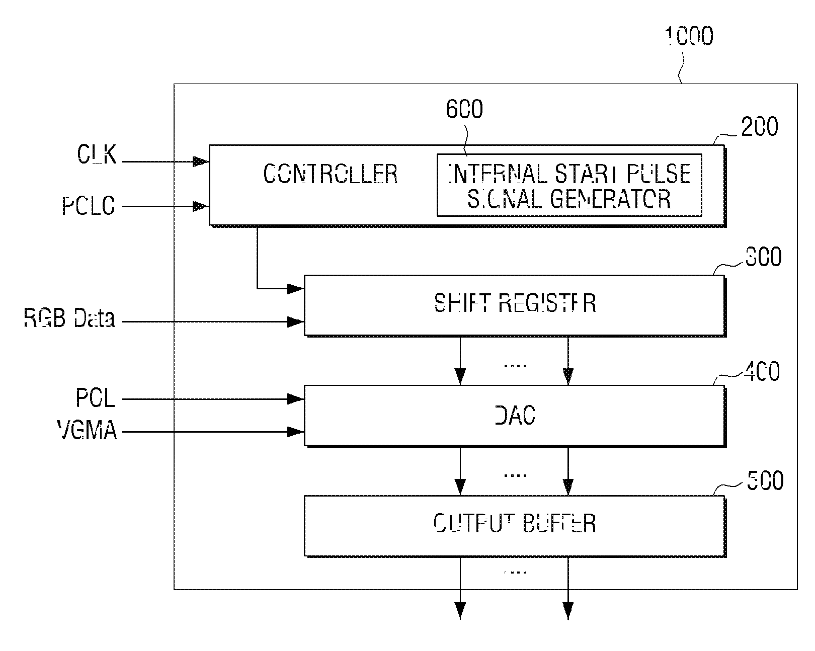
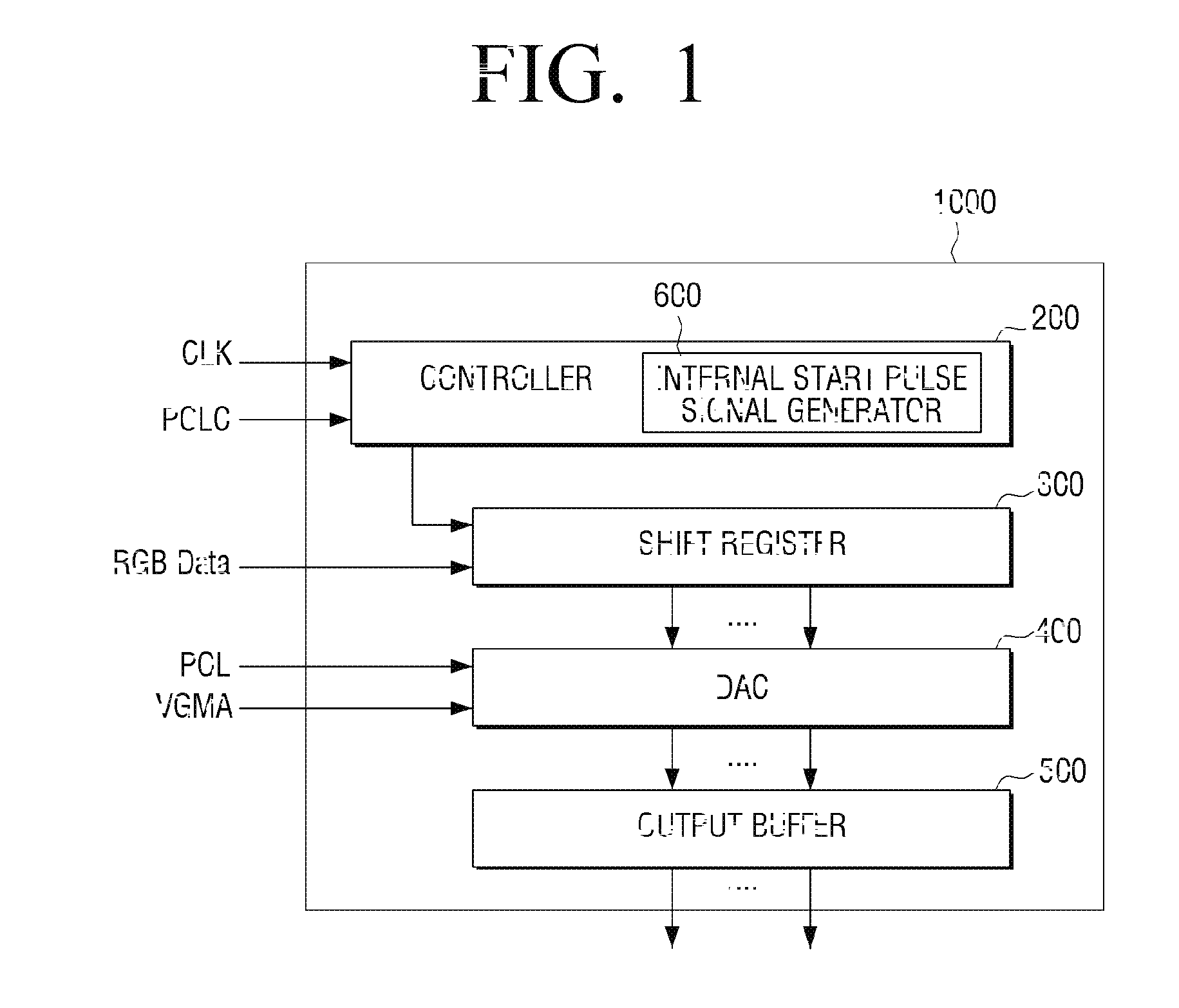
[0039]FIG. 1 is a block diagram illustrating an example of a source driver 1000 according to an embodiment. As is shown in FIG. 1, the source driver 1000 includes a controller 200, a shift register 300, a digital-to-analog converter (DAC) 400, and an output buffer 500.

[0040]The controller 200 receives a clock signal CLK and a polarity conversion signal POLC. The controller 200 may receive the clock signal CLK and the polarity conversion signal POLC from a timing circuit (not shown) which is disposed outside the source driv...


PUM


Abstract

A source driver, a controller, and a method for driving a source drive are provided. The source driver includes a controller configured to receive a start pulse signal, and generate and output one of a new start pulse signal if the start pulse signal is received, and an internal start pulse signal if the start pulse signal is not received, a shift register configured to receive video data, store the video data, and output the video data if the outputted start pulse signal is received by the shift register, a digital-to-analog converter (DAC) configured to convert the video data output from the shift register into an analog voltage signal, and output the analog voltage signal, and an output buffer configured to buffer the analog voltage signal output from the DAC, and output the buffered analog voltage signal.

Description

CROSS-REFERENCE TO RELATED APPLICATION[0001]This application claims the benefit under 35 U.S.C. §119(a) of Korean Patent Application No. 10-2011-0010661 filed on Feb. 7, 2011, in the Korean Intellectual Property Office, the entire disclosure of which is incorporated herein by reference for all purposes.BACKGROUND[0002]1. Field[0003]The following description relates to a source driver, a controller, and a method for driving a source driver that serve to generate a signal to read video data.[0004]2. Description of the Related Art[0005]A liquid crystal display (LCD) apparatus is an apparatus that converts video data into electric signals and inputs the electric signals. According to an electric driving signal applied to an LCD apparatus, pixels of a liquid crystal layer of the LCD apparatus are controlled to be in a light penetration state or a light interruption state by a transistor included in each of the pixels. Under such control, hundreds of thousands or millions of pixels consti...

Claims


Application Information

Patent Timeline
Patent Type & Authority Applications(United States)
IPC IPC(8): H04N7/01
CPCG09G3/3611G09G2310/027G09G2330/06G09G2320/0693G09G2330/021G09G2310/08
Inventor CHOI, JIN-CHOKANG, JEONG-SOOSUL, JUNG-HOONKIM, JUNG-HYUNCHUNG, KYU-YOUNG
Owner MAGNACHIP SEMICONDUCTOR LTD
Why Eureka
Try Eureka