Direct fuel injection internal combustion engine

Active Publication Date: 2005-06-30
NISSAN MOTOR CO LTD
View PDF6 Cites 13 Cited by
  • Summary
  • Abstract
  • Description
  • Claims
  • Application Information

AI Technical Summary

Benefits of technology

[0008] The direct fuel injection internal combustion engine with the recessed part described in the above mentioned publication alleviates the layout limitation of the fuel injector and the spark plug in the cylinder head. Moreover, the tapered shape of the recessed part prevents a problem of a fuel stream adhering to a wall surface of the recessed part. However, when the recessed part is merely tapered just wide enough to prevent the fuel stream from adhering to the wall surface, there are some problems still remained.
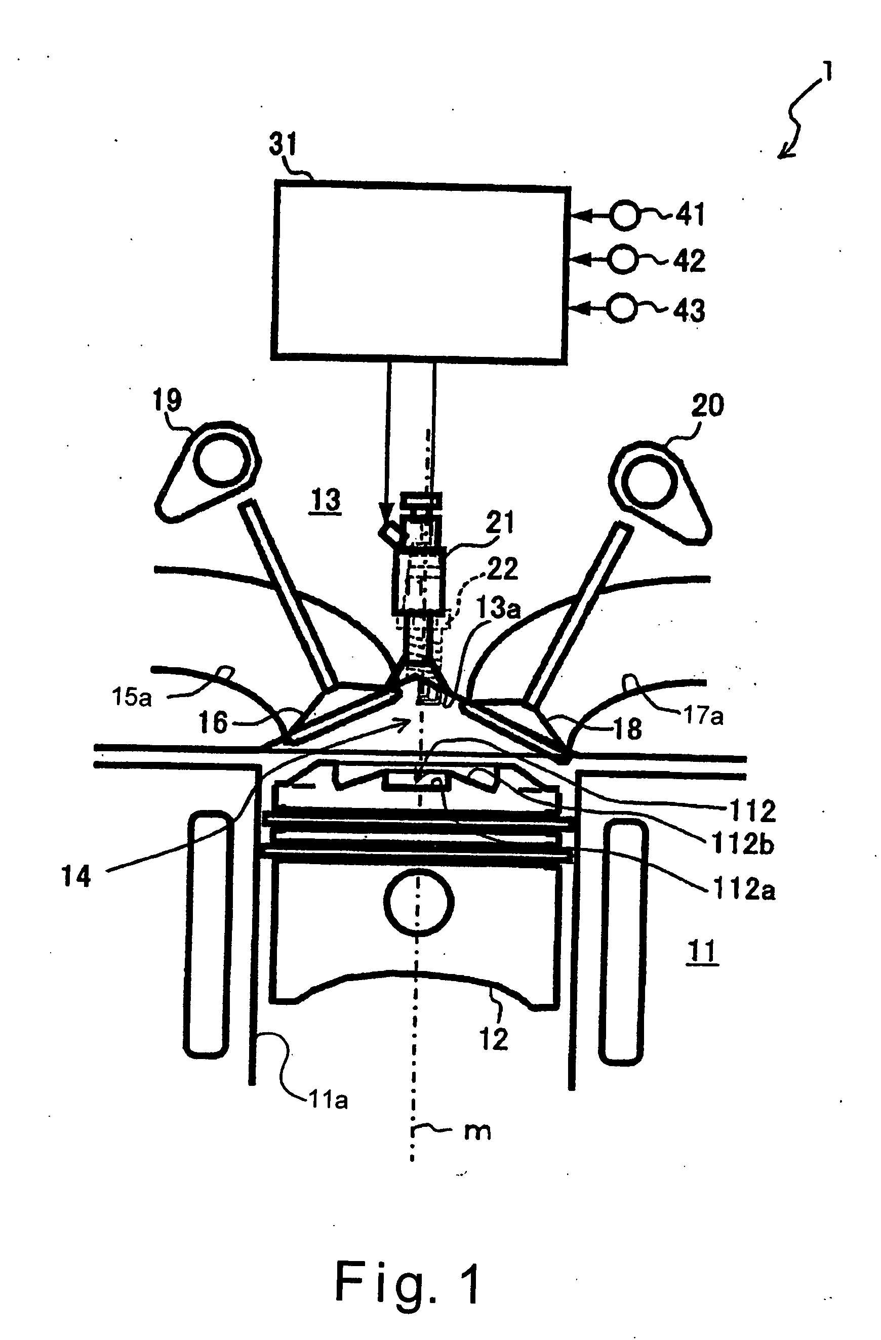
[0010] Accordingly, one object of the present invention is to provide a direct fuel injection internal combustion engine that can suppress a generation of negative pressure inside the recessed part so that the desired shape of fuel stream can be achieved when the fuel injector is arranged above a center portion of the piston and positioned higher than the combustion chamber upper surface of the cylinder head.

Problems solved by technology

However, when the recessed part is merely tapered just wide enough to prevent the fuel stream from adhering to the wall surface, there are some problems still remained.
In such case, a desired shape of the fuel stream cannot be achieved in the combustion chamber.
However, a problem of interference between the recessed part and intake ports and / or exhaust ports limits the degree to which the taper angle can be widened when the fuel injector is arranged along or near the center axis of the cylinder.

Method used


Image

  • Direct fuel injection internal combustion engine
  • Direct fuel injection internal combustion engine
  • Direct fuel injection internal combustion engine

Examples


second embodiment

[0062] Referring now to FIGS. 9 to 12, a second embodiment will now be explained. In view of the similarity between the first and second embodiments, the parts of the second embodiment that are identical to the parts of the first embodiment will be given the same reference numerals as the parts of the first embodiment. Moreover, the descriptions of the parts of the second embodiment that are identical to the parts of the first embodiment may be omitted for the sake of brevity.

[0063] The second embodiment is basically identical to the first embodiment except for an arrangement of a recess portion R5 of a cylinder head 513. FIG. 9 is a partial cross sectional view of a portion of the cylinder head 513 in accordance with the second embodiment of the present invention. The cross sectional view shown in FIG. 9 is taken along a plane that is parallel to the direction in which the cylinder bores 11 a are arranged.

[0064] As seen in FIG. 9, in the second embodiment, a second wall section 5...

third embodiment

[0070] Referring now to FIGS. 13(a) to 13(c) and 14(a) to 14(c), a third embodiment will now be explained. In view of the similarity between the first and third embodiments, the parts of the third embodiment that are identical to the parts of the first embodiment will be given the same reference numerals as the parts of the first embodiment. Moreover, the descriptions of the parts of the third embodiment that are identical to the parts of the first embodiment may be omitted for the sake of brevity. The parts of the third embodiment that differ from the parts of the first embodiment will be indicated with a single prime (′).

[0071]FIG. 13(a) is a simplified bottom plan view of a combustion chamber upper surface 813a of a cylinder head 813 in accordance with the third embodiment of the present invention. The cylinder head 813 of the third embodiment is basically identical to the cylinder head 13 of the first embodiment except for an arrangement of a recess portion R8 formed by a perip...


PUM


Abstract

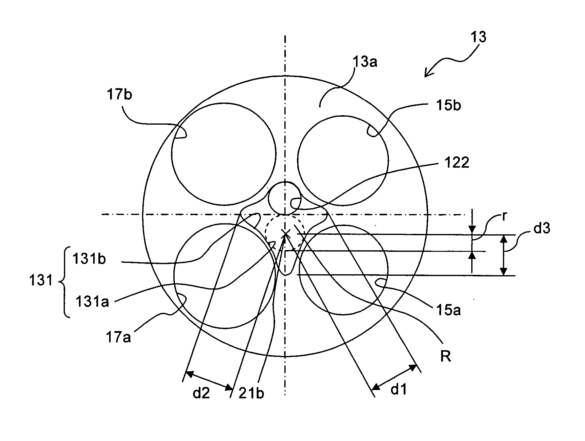
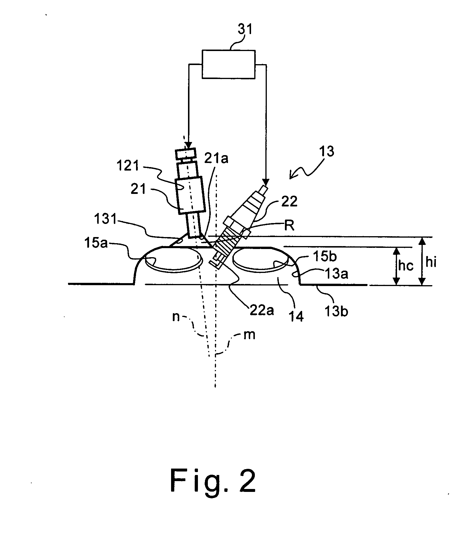
A direct fuel injection internal combustion engine includes a fuel injector arranged above a center portion of the piston and positioned higher than a combustion chamber upper surface of a cylinder head. The cylinder head includes a recess portion in which a tip of the fuel injector is disposed in a cross sectional view of the cylinder head in a plane perpendicular to a fuel injection center axis. The recess portion is provided with a channel extending longitudinally away from the tip of the fuel injector configured and arranged to reduce negative pressure within the recess portion. The channel is oriented in such a direction as to avoid the interference between the channel and other parts of the cylinder head. When the fuel injector is a multi-hole fuel injector, the channel can be oriented toward a direction along a centerline between two adjacent injection vents of the fuel injector.

Description

BACKGROUND OF THE INVENTION [0001] 1. Field of the Invention [0002] The present invention relates to a direct fuel injection internal combustion engine in which a fuel is directly injected into a combustion chamber. More particularly, the present invention relates to a direct fuel injection internal combustion engine in which a fuel injector is installed in a cylinder head above a center portion of a piston and positioned higher than a combustion chamber top surface formed by the cylinder head. [0003] 2. Background Information [0004] In a conventional direct fuel injection internal combustion engine, a fuel injector is arranged so that a tip of the fuel injector faces in a combustion chamber. Such conventional direct fuel injection internal combustion engine is configured and arranged to perform stratified combustion by injecting fuel from the fuel injector during a compression stroke to form a stratified fuel-air mixture in a prescribed operating region. In such conventional direct...

Claims


Application Information

Patent Timeline
IPC IPC(8): F02B23/10F02M61/18
CPCY02T10/125F02B23/101Y02T10/12
Inventor TANAKA, DAISUKEHIRAYA, KOJIHOTTA, ISAMUTSUCHIDA, HIROFUMI
Owner NISSAN MOTOR CO LTD
Why Eureka
Try Eureka