Multi-antenna system

A multi-antenna system and radiating element technology, which is applied in the field of multi-antenna systems, can solve the problems that the inductance is not easy to model, it is difficult to predict the frequency, and there are many restrictions on components.

Active Publication Date: 2012-11-07
REALTEK SEMICON CORP
View PDF0 Cites 0 Cited by
  • Summary
  • Abstract
  • Description
  • Claims
  • Application Information

AI Technical Summary

Problems solved by technology

[0003] However, traditional methods of increasing antenna isolation have many layout constraints
For example, if a slit is used, the slit can only be placed on the ground plane, and the capacitance and inductance generated by the slit on the ground plane cannot be replaced by other capacitance and inductance, which will make the components There are more restrictions
In addition, since the generated inductance is not easy to model, it is also difficult to predict the frequency of the bandstop effect.
More importantly, due to the limitations of the above-mentioned various layouts, the traditional method of increasing antenna isolation will inevitably occupy a large area

Method used


Image

  • Multi-antenna system
  • Multi-antenna system
  • Multi-antenna system

Examples


Embodiment Construction

[0033] The aforementioned and other technical contents, features and effects of the present invention will be clearly presented in the following detailed description of the two embodiments with reference to the accompanying drawings.

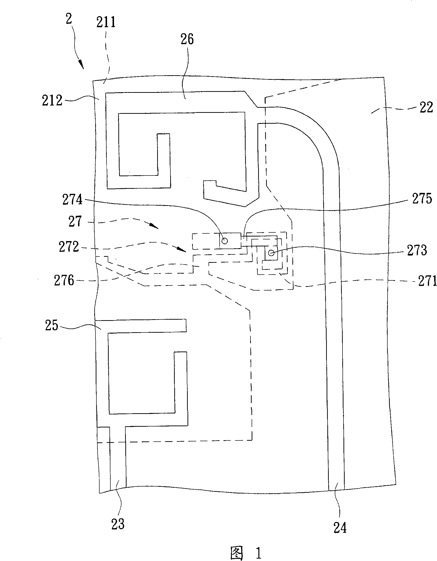
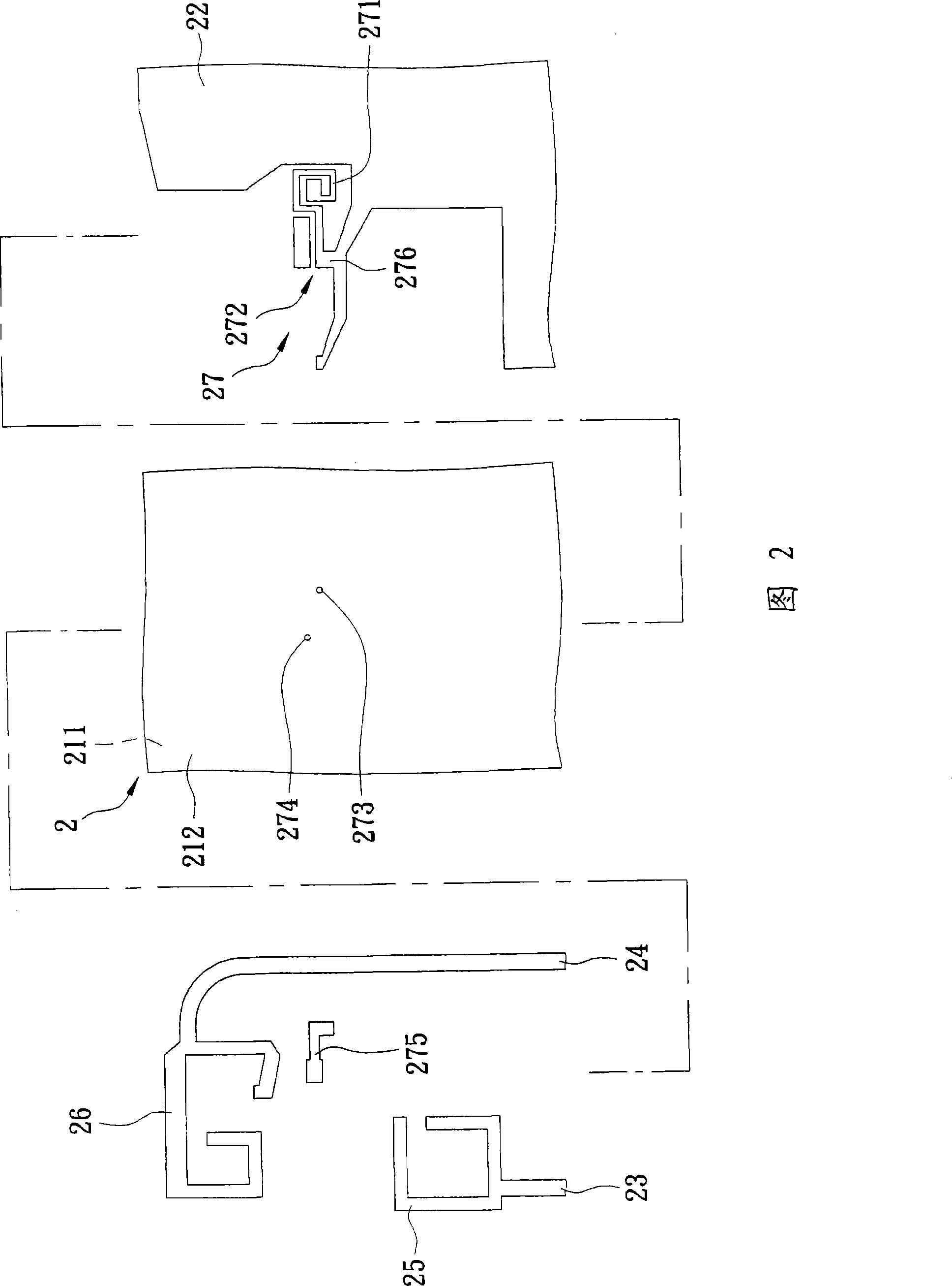
[0034] see figure 1 and figure 2 , which shows an embodiment of the multi-antenna system of the present invention, including a dielectric layer 21, a ground plane 22, two feed lines 23, 24, two radiating elements 25, 26 and an isolation unit 27, to form two printed antennas . The dielectric layer 21 is made of a dielectric material and includes a first surface 211 and a second surface 212 that are substantially parallel to each other. The ground plane 22 is made of conductive material and printed on the first surface 211 of the dielectric layer 21 . The two feed lines 23 , 24 are made of conductive material, printed on the second surface 212 of the dielectric layer 21 , and overlap with the ground plane 22 . The two radiating elements 25 , ...


PUM


Abstract

The invention provides a multiaerial system used for reducing layout limit and element limit, comprising two aerials and an isolation cell. The isolation cell is arranged between the two aerials and comprises an inductance which is a ring formed by coupling and a capacitance; wherein, the inductance and the capacitance are excited for resonance on the resonance frequency which is the same as the operation frequency of the two aerials substantially, so as to increase the isolation of the two aerials.

Description

technical field [0001] The present invention relates to a multi-antenna system, in particular to a multi-antenna system capable of increasing antenna isolation. Background technique [0002] In today's wireless communication systems, multiple antennas with substantially the same operating frequency are often used simultaneously to transmit or receive signals, so as to improve transmission performance without increasing power or bandwidth. In order to achieve the purpose of miniaturization, these antennas will be arranged closely, which will cause mutual interference. Therefore, how to increase the isolation of these antennas has become an important issue. [0003] However, traditional methods of increasing antenna isolation have many layout constraints. For example, if a slit is used, the slit can only be placed on the ground plane, and the capacitance and inductance generated by the slit on the ground plane cannot be replaced by other capacitance and inductance, which wil...

Claims


Application Information

Patent Timeline
Patent Type & Authority Patents(China)
IPC IPC(8): H01Q1/38H01Q1/52H01Q21/28
Inventor 钟世忠林明达蔡志鸿
Owner REALTEK SEMICON CORP
Why Eureka
Try Eureka