cobra antenna

A technology of cobra and antenna, applied in the direction of antenna, resonant antenna, antenna components, etc., can solve the problems of increasing antenna impedance and decreasing impedance, and achieve the effect of reducing restrictions

Inactive Publication Date: 2016-02-10
SONY CORP
View PDF4 Cites 0 Cited by
  • Summary
  • Abstract
  • Description
  • Claims
  • Application Information

AI Technical Summary

Problems solved by technology

For example, it has been reported that when the number of windings is one, the impedance of the antenna tends to increase even if the frequency exceeds 100 MHz; however, when the number of windings is three times, the impedance decreases sharply

Method used


Image

  • cobra antenna
  • cobra antenna
  • cobra antenna

Examples


Embodiment Construction

[0026] The following will be based on Figure 1 to Figure 4 Exemplary embodiments of the present invention will be described, and will be described in the following order.

[0027] 1. Description of the basic structure and basic principles of the Cobra antenna

[0028] 2. Structure and characteristics of the cobra antenna according to the exemplary embodiment of the present invention

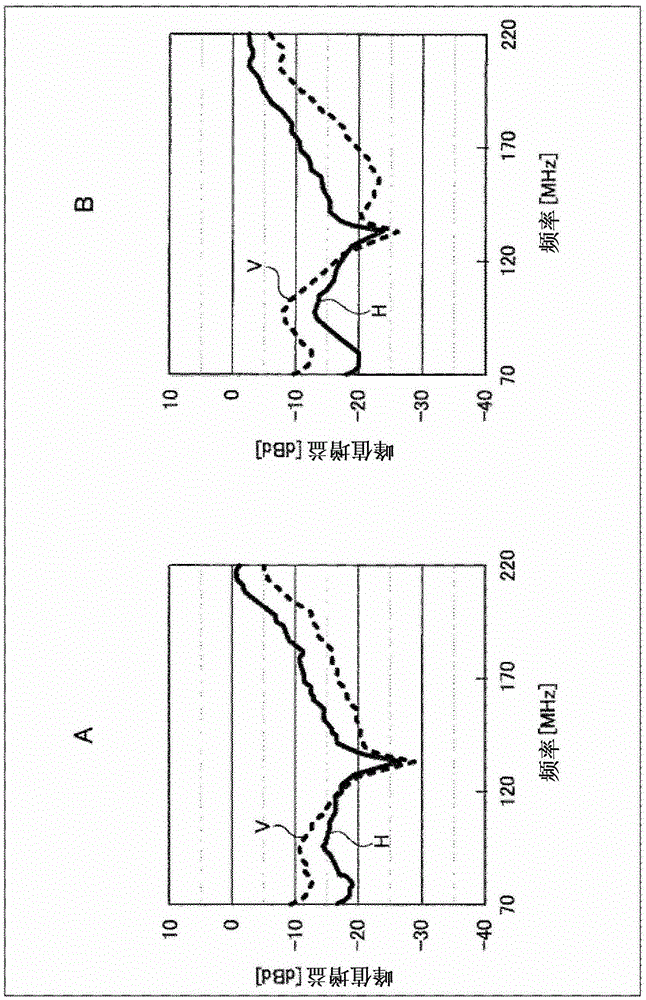
[0029] 3. Field Tests Performed Using Cobra Antennas of Exemplary Embodiments of the Invention

[0030]

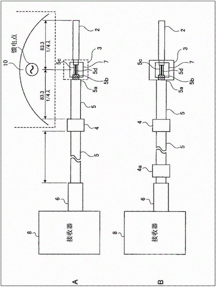
[0031] figure 1 A shows the Figure 5 The conventional Cobra antenna shown is the same as the Cobra antenna. figure 1 B shows the cobra antenna of this example. First, describe figure 1 A and figure 1 Commonality between B.

[0032] figure 1 A and figure 1 Each cobra antenna 10 shown in B includes an antenna element 2 , a relay portion 3 , a coaxial wire 5 and a core 4 . Assuming that the wavelength of radio waves to be received is λ, the length of the antenna element 2 is ...


PUM


Abstract

The present invention relates to a small cobra antenna that has a high performance as an antenna gain, and minimizes the effect of the length of the coaxial wire. An antenna element and a coaxial wire are connected to a junction that is a feeding point. The antenna element has a length corresponding to the frequency of a broadcast wave to be received. Further, a ferrite core is positioned at a location a length identical to the length of the antenna element away from the junction. The coaxial wire is wound around the ferrite core about once to three times. A high frequency interrupting part for interrupting the high-frequency current from the coaxial wire is provided at the front side of a connecter of a receiver to which the other end of the coaxial wire is connected.

Description

technical field [0001] The present invention relates to a cobra antenna which can be used as an antenna for a wide frequency band range from FM band to UHF band and which can be realized with a simple structure. Background technique [0002] Various forms of antennas are generally used as antennas for receiving various broadcast waves such as TV broadcasts or FM broadcasts. For example, dipole antennas or Yagi-Uda antennas (Yagi-Udaantenna) are commonly used to receive TV broadcasts and FM radio. [0003] On the other hand, various broadcast waves are increasingly being received indoors, in a car, or while walking. Antennas used in such cases must be easy to handle, for example, to fit or install. [0004] Such easy-to-assemble or easy-to-handle antennas are typified by dipole antennas realized with simple-structural antenna elements. A cobra antenna is known as a specific embodiment of a dipole antenna. The cobra antenna is used by winding several turns of a coaxial wir...

Claims


Application Information

Patent Timeline
Patent Type & Authority Patents(China)
IPC IPC(8): H01Q9/16
CPCH01Q1/3291H01Q9/16H01Q9/30
Inventor 吉野功高坪井觉
Owner SONY CORP
Why Eureka
Try Eureka