Supercharge Your Innovation With Domain-Expert AI Agents!

Lock mechanism of sliding member and transfer device

a technology of sliding member and lock mechanism, which is applied in the directions of erasing devices, transportation and packaging, paper hanging, etc., to achieve the effect of effective prevention

Active Publication Date: 2005-06-30
KOKUYO CO LTD
View PDF4 Cites 13 Cited by
  • Summary
  • Abstract
  • Description
  • Claims
  • Application Information

AI Technical Summary

Benefits of technology

The lock mechanism of this patent is designed to hold a sliding member in a specific position and allow it to move in a sliding manner. The mechanism includes an engagement portion that prevents the sliding member from moving when an operating force is applied to only one location on the sliding member. The engagement can be easily released with a little force applied to the sliding member, making it easy for users to operate the sliding member with one finger. The lock mechanism can be used in a transfer device to transfer materials to an object. The sliding member has a contacting portion that can be operated with a finger, and the mechanism allows for separate movement of the sliding member from the engaged position to the pullout position. The engagement portion is formed by an engaging bore on the sliding member and an engaging projection on the case. The technical effects of this lock mechanism include improved usability and convenience for users and efficient operation of the sliding member.

Problems solved by technology

More specifically, it is possible to operate the sliding member without grasping to pinch the body even though it is not possible to grasp to pinch the body because only one finger is free.

Method used


Image

  • Lock mechanism of sliding member and transfer device
  • Lock mechanism of sliding member and transfer device
  • Lock mechanism of sliding member and transfer device

Examples


Embodiment Construction

[0033] An embodiment of the present claimed invention will be described in detail with reference to the accompanying drawings.

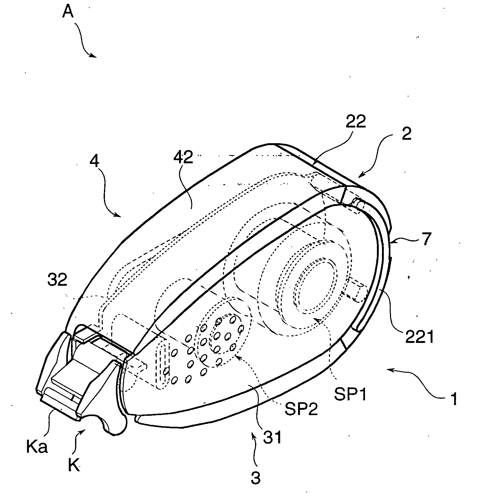
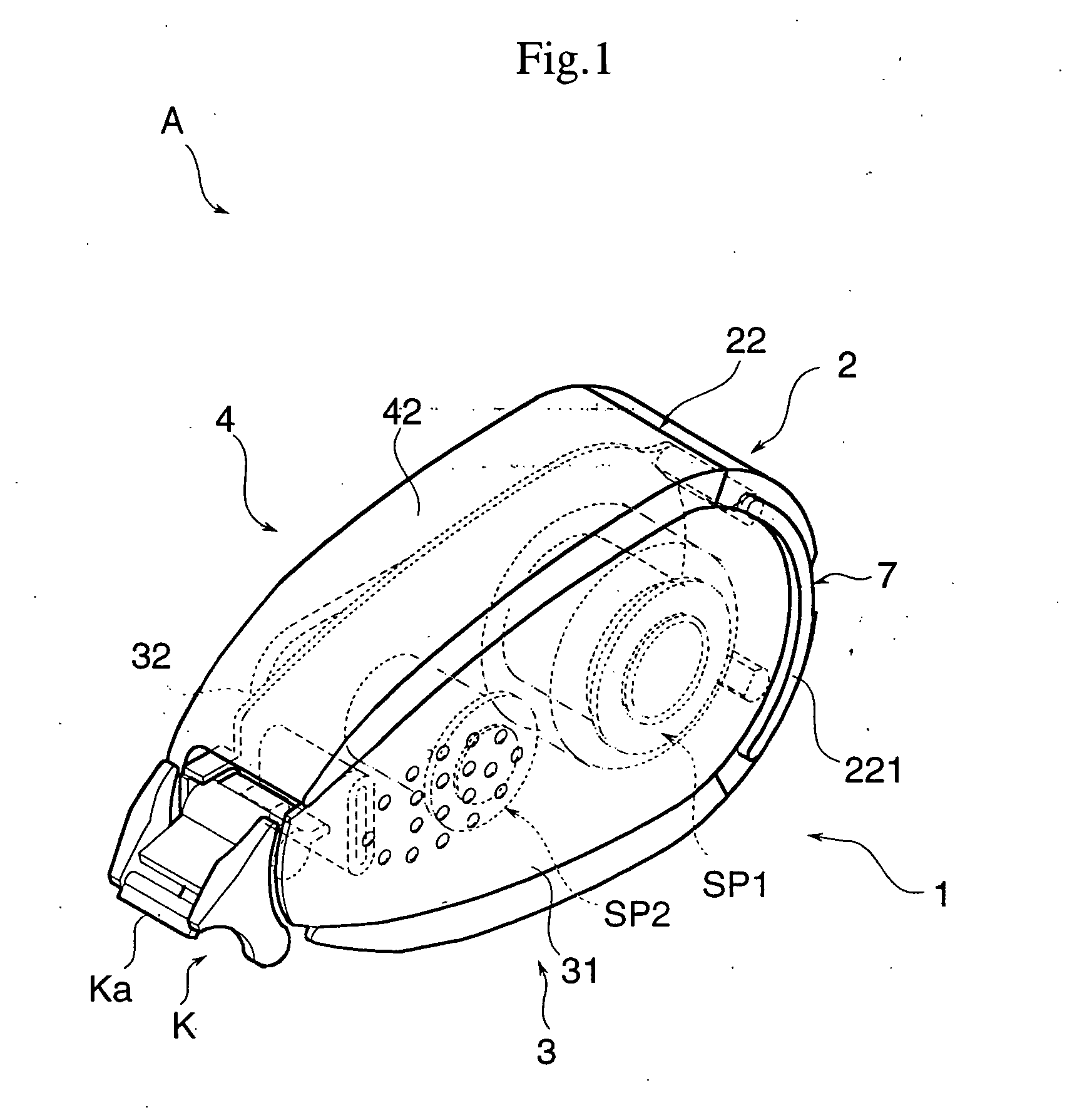
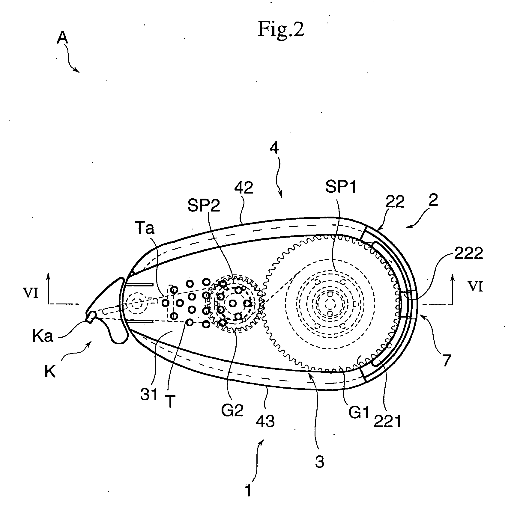
[0034] The embodiment shown in FIG. 1, FIG. 2 and FIG. 3 is a transfer device A that accommodates a tape T comprising a tape body Ta and a transfer paste, not shown in drawings, as being a transferring material that is adhered to a single face of the tape body Ta in a predetermined pattern, and is used for transferring the transfer paste on an object on which the transfer paste is to be transferred such as paper.

[0035] The transfer device A comprises a body 1 inside of which the tape T can be accommodated, and a sliding member 2 that has an elasticity and that is mounted in a state of contacting along the body 1 between a predetermined engaged position shown in FIG. 5(a) and FIG. 7(a) and a pullout position shown in FIG. 5(b) and FIG. 7(b) in a slidably movable manner. Further, the body 1 has a generally halved arrangement comprising two members, one of whi...


PUM

PropertyMeasurementUnit
operating forceaaaaaaaaaa
widthaaaaaaaaaa
circumferenceaaaaaaaaaa

Abstract

A transfer device A comprising a body 1 having a cartridge 3 that holds a tape (not shown in drawings) one face of which transfer paste as being a material to be transferred is affixed and a transfer head K and a case 4 that stores the cartridge 3 and a sliding member 2 is provided with a lock mechanism RR that has an engaging portion 5 that is arranged between the body 1 and the sliding member 2 mounted on the body 1 in a slidably movable manner between an engaged position and a pullout position and that holds the sliding member 2 at the engaged position by making use of a concavo-convex engagement and an engagement release mechanism 6 that releases the engaged state of the engaging portion so as to allow the sliding member to make a sliding movement by applying an operating force to an operating portion 221 arranged on only one location of the sliding member 2 from the engaged position toward the pullout position along a direction of a sliding movement and toward a direction different from the direction of the sliding movement simultaneously.

Description

BACKGROUND OF THE INVENTION AND RELATED ART STATEMENT [0001] This invention relates to a lock mechanism that holds a sliding member that is mounted on a body as being an object to be mounted in a slidably movable manner between a predetermined engage position and a pullout position and a transfer device that makes use of the lock mechanism. [0002] Various transfer devices that are used in case of transferring a transferring material such as a tape like an adhesive tape or a non-adhesive tape, a solid or liquid paste or a binding agent to a face to which the transferring material is to be transferred have been conceived. Some of the transfer devices are so arranged that a holder holding a transferring material comprises a body case and a cartridge holding the transferring material wherein the holder and the cartridge can be split. In accordance with this arrangement, the holder is split into the cartridge and the body case and the cartridge holding the used transferring material is e...

Claims


Application Information

Patent Timeline
Patent Type & Authority Applications(United States)
IPC IPC(8): B43M11/02B43M11/06B43L19/00B65H35/07B65H37/00
CPCB43M11/06B65H37/007Y10T156/1705Y10T156/1795Y10T156/18Y10T156/1788Y10T156/1348
Inventor MITSUI, TAKASHISHIMA, HIDETO
Owner KOKUYO CO LTD
Features
  • R&D
  • Intellectual Property
  • Life Sciences
  • Materials
  • Tech Scout
  • Unparalleled Data Quality
  • Higher Quality Content
  • 60% Fewer Hallucinations
Learn More