Method for producing thin film heating element and heating device using same

a heating element and heating device technology, applied in the direction of heating elements, ohmic-resistance heating, printing, etc., can solve the problems of substrate damage in its external shape, inconvenient use of heating elements, and hindering the formation of thin films, etc., to reduce thermal stress, increase thermal resistance, and low thermal expansion property

Inactive Publication Date: 2004-05-27
PARK SUNG DON
View PDF5 Cites 16 Cited by
  • Summary
  • Abstract
  • Description
  • Claims
  • Application Information

AI Technical Summary

Benefits of technology

0018] It is particularly advantageous to employ a transparent glass or ceramic having an increased thermal resistance and a low thermal expansion property, as a base material on which a heat generating portion is formed. The ceramic comprises semicrystalline ceramic including one or more crystalline phases. Aluminum oxide, petalite, mullite, cordierite, ceramic products Nos. N-0, N-11, GC190 produced by NEG (Nippon Electric Glass Co., Ltd.) and a quartz plate or tube can be used. Preferably, these materials should have a thermal expansion coefficient less than 3.times.10.sup.-6 / .degree. C. within a temperature range of 0 to 300.degree. C. so as to reduce thermal stress.
0019] The surface of the material except the heat generating portion is masked with heat- and oil-resistant ink which is then allowed to run dry. In addition, the material is preheated up to a temperature of 500 to 800.degree. C. and the conductive composition for the heating element is sprayed on the surface of the preheated material so as to form a thin film. In the process of spraying the conductive composition for the heating element, clean air from which impurities including water and oil have been removed is used as a carrier. In a case where the spraying is performed on the same material under the same spaying conditions, a thin film which has a low electric resistance and excellent visible light transmissivity at a high temperature can be obtained.

Problems solved by technology

However, since the conductive thin film has insufficient heat resistance, impact resistance, chemical resistance and close adherence between the material and the conductive thin film, it is not suitable for use in a heating element.
Thus, there is a problem in that the formation of the thin film is hindered.
Thus, there is another problem in that the substrate is damaged in its external shape.
Thus, there is a further problem in that the metallic thin film is broken and cannot function as a heating device in a case where an operating voltage or lower is applied to the film.

Method used


Image

  • Method for producing thin film heating element and heating device using same
  • Method for producing thin film heating element and heating device using same
  • Method for producing thin film heating element and heating device using same

Examples


second embodiment

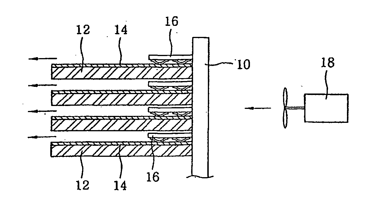
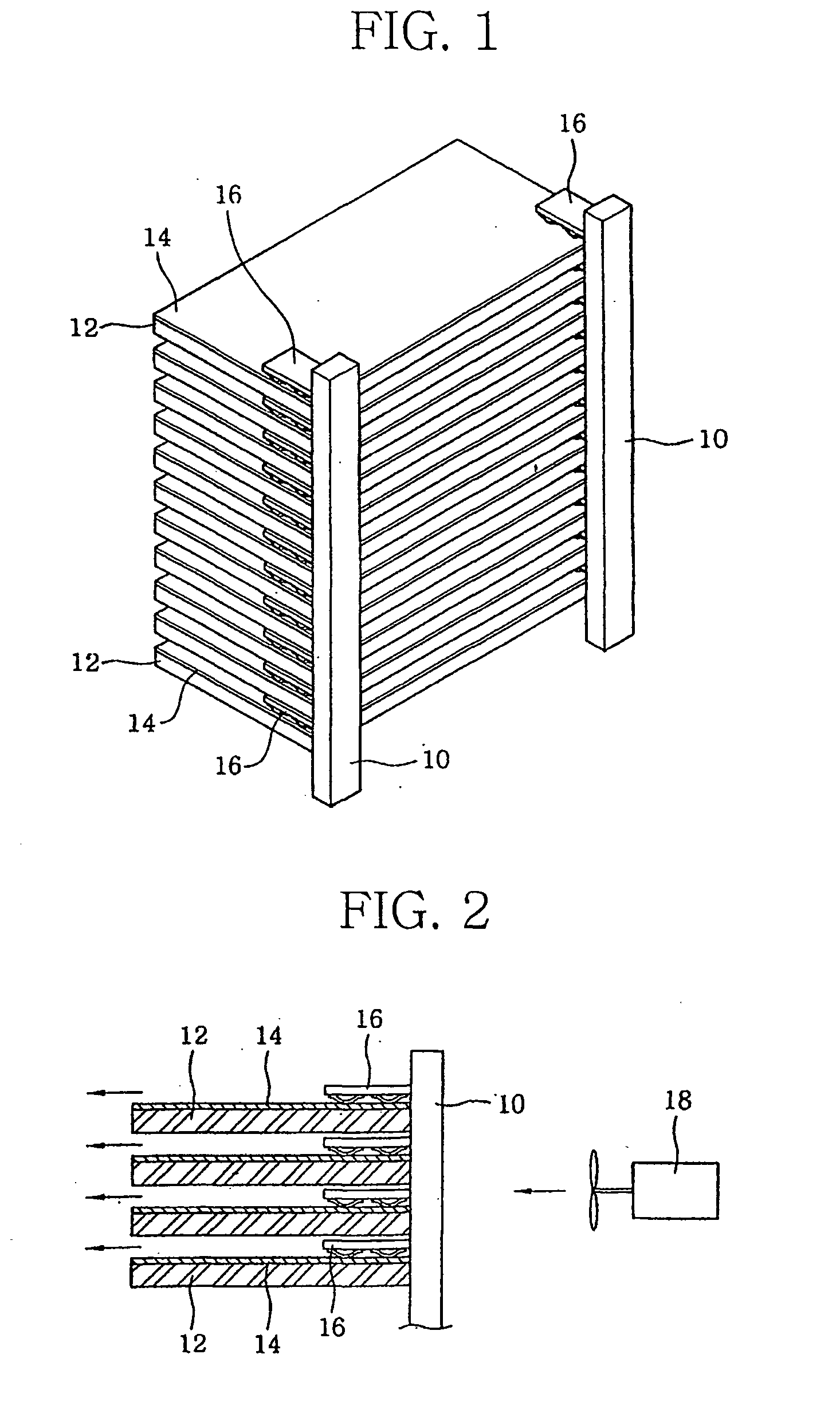
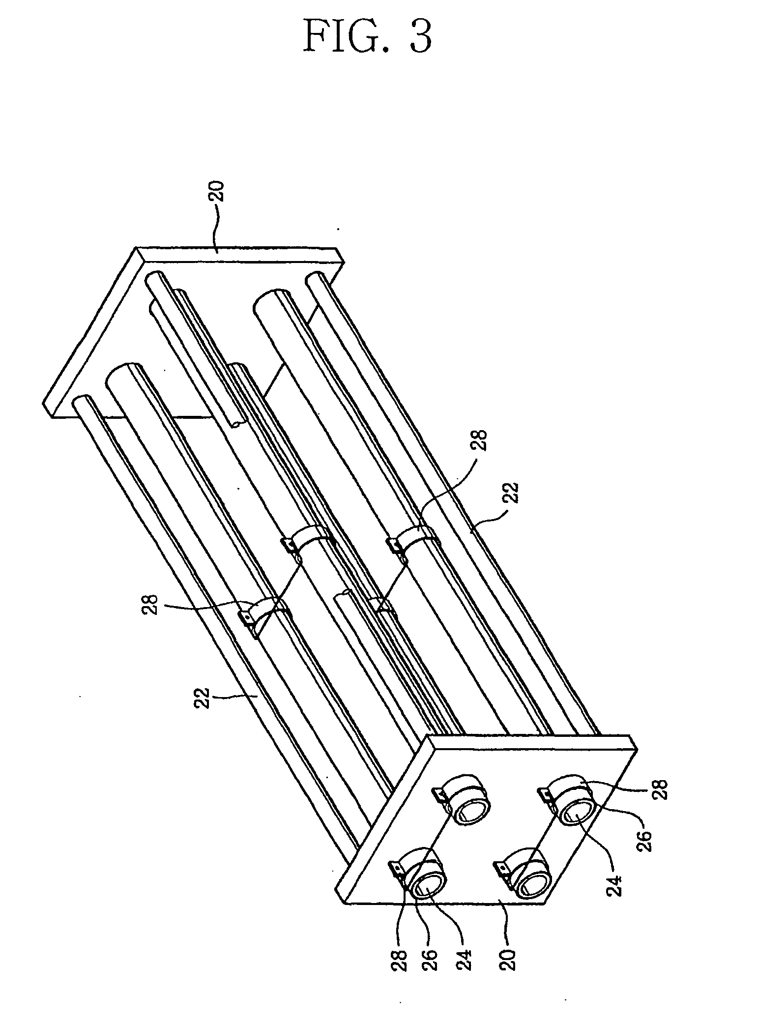
[0033] The heat generating portions 14, 26 of the heating devices of the first and second embodiment produced by the thin film heating element according to the present invention can generate heat of high temperature and have a excellent durability. Further, the heat generating portions can be easily formed into a desired shape and have very high thermal efficiency as compared with their power consumption. Although the substrates 12 and tubes 24 on which the heat generating portions 14, 24 are respectively formed are of flat or cylindrical shape in the illustrated embodiments, they may be formed into a circular, elliptical or other desired shape.

third embodiment

[0034] Referring finally to FIGS. 5 and 6, there is illustrated a heating device according to the present invention.

[0035] The heating device shown in FIGS. 5 and 6 comprises an inner container 40 which includes an upper inlet port 42 of a. slender tubular shape, through which liquid such as water can be easily introduced, and a lower drain port 44. An outer container 48 surrounding the inner container 40 is provided at an outer side of the inner container 40 so as to form a channel 46 through which the liquid discharged from the drain port 44 can flow, and an upper end of the outer container 48 is integrally formed with that of the inner container 40. An upper portion of the outer container 48 is formed with a drain port 50 which remains in communication with the channel 46. A connecting portion 52 which integrally connects the inner container 40 and the outer container 48 to reinforce their strength is formed at a lower portion of a space between the two containers.

[0036] In addit...


PUM

PropertyMeasurementUnit
temperatureaaaaaaaaaa
thicknessaaaaaaaaaa

Abstract

A method of producing a thin film heating element is provided which can be used in manufacturing a transparent thin film heating element of desired shape with an increased heat emission property and an excellent durability. Also provided is a heating device of the type incorporating the thin film heating element produced by this method. The inventive method comprises the steps of, applying heat- and oil-resistant ink on a predetermined surface area of a base element, allowing the ink to run dry, spraying conductive chemical composition on the base element to form a conductive thin heater film, removing the ink out of the base element, printing a thin film electrode leading to the thin heater film, and baking the base element into a thin film heating element.

Description

[0001] The present invention relates to a method of producing a thin film heating element whereby the thin film heating element which is transparent and excellent in heat generating property and durability can be easily produced into a desired shape. The invention is also directed to a heating device that makes use of the thin film heating element.[0002] In order to form a conductive thin film on a surface of a material, a dipping process, a vacuum deposition process, a sputtering process, a spraying process, and the like are generally used. Since the conductive thin film is usually formed at a temperature of 300.degree. C. or lower according to the dipping method, the vacuum deposition method or the sputtering method, the shape of the coated material is kept unchanged, meaning that the conductive thin film is suitable for producing a transparent electrode of a flat panel display device, for preventing dew condensation and for the manufacture of an anti-static glass. However, since ...

Claims


Application Information

Patent Timeline
Patent Type & Authority Applications(United States)
IPC IPC(8): H05B3/20
CPCH05B3/20H05B2203/017H05B2203/013H05B3/00
Inventor PARK, SUNG-DON
Owner PARK SUNG DON
Why Eureka
Try Eureka