Method of manufacturing a semiconductor device

a manufacturing method and semiconductor technology, applied in the direction of semiconductor devices, electrical appliances, transistors, etc., can solve the problems of increasing off, deteriorating reliability, and phenomena becoming large reliability problems, and achieve the effect of reducing light intensity and forming with eas

Inactive Publication Date: 2007-01-30
SEMICON ENERGY LAB CO LTD
View PDF28 Cites 17 Cited by
  • Summary
  • Abstract
  • Description
  • Claims
  • Application Information

AI Technical Summary

Benefits of technology

[0015]A pattern having a function of lowering the intensity of exposure light is established in edge portions of one side, or both sides, of a mask pattern used for forming a gate electrode in a photomask, or in a reticle, for forming the gate electrode used by a photolithography process. (This pattern is referred to as a supplemental pattern within this specification.) A diffraction grating pattern having a slit portion composed of lines and spaces below the limit of image resolution of exposure apparatus, and a translucent film for lowering the transmittivity of the exposure light, can be considered as specific patterns for the supplemental pattern having the capability of reducing the intensity of exposure light. The intensity of transmitted light can be regulated by controlling the pitch and the slit width of a slit (space) portion when the diffraction grating pattern is used. On the other hand, the intensity of the light transmitted can be regulated by controlling the transmittivity of the translucent film when the translucent film is used.
[0069]It is possible to establish the means for reducing the intensity of light in an arbitrary mask pattern, and therefore GOLD structure, LDD structure, and single drain structure transistors can be formed with ease in each of the circuits of the semiconductor device.

Problems solved by technology

However, when polycrystalline silicon TFTs are used, phenomena such as a reduction in the mobility and the on current (the electric current flowing when a TFT is in an on state), and an increase in the off current (the electric current flowing when the TFT is in an off state) are observed as deterioration of reliability, and there are times when these phenomena become large problems with respect to reliability.
However, the voltage resistance of the drain increases greatly for the LDD structure case compared with a single drain structure, and the resistance of the low concentration impurity regions (n−regions or p−regions) is large, and thus a disadvantage of a reduction in the drain current exists.
The low concentration impurity regions (n−regions or p−regions) are depleted, and a degradation mode in which there is an additional increase in resistance, peculiar to the LDD, becomes a problem.
On the other hand, a low concentration impurity region (n−region or p−region) of the LDD structure is formed overlapping with edge portions of the gate electrode with the GOLD structure, and although it is a larger effect against hot carriers compared to the LDD structure, it also has a disadvantage in that the value of the off current becomes large.
However, there is a problem in that the film formation processes and the etching processes become complex if a two layer gate electrode structure is used.
The formation of LDD structures and GOLD structures is performed by using processes such as dry etching only, and all of the transistors in the semiconductor device have the same structure; therefore there is a problem in that single drain structures, LDD structures, and GOLD structures cannot be formed separately for each circuit.
Problems such as a restriction developing in the length of the low concentration impurity region (n−region or p−region), and an inability to sufficiently secure the length, therefore develop.

Method used


Image

  • Method of manufacturing a semiconductor device
  • Method of manufacturing a semiconductor device
  • Method of manufacturing a semiconductor device

Examples


embodiment mode 1

[Embodiment Mode 1]

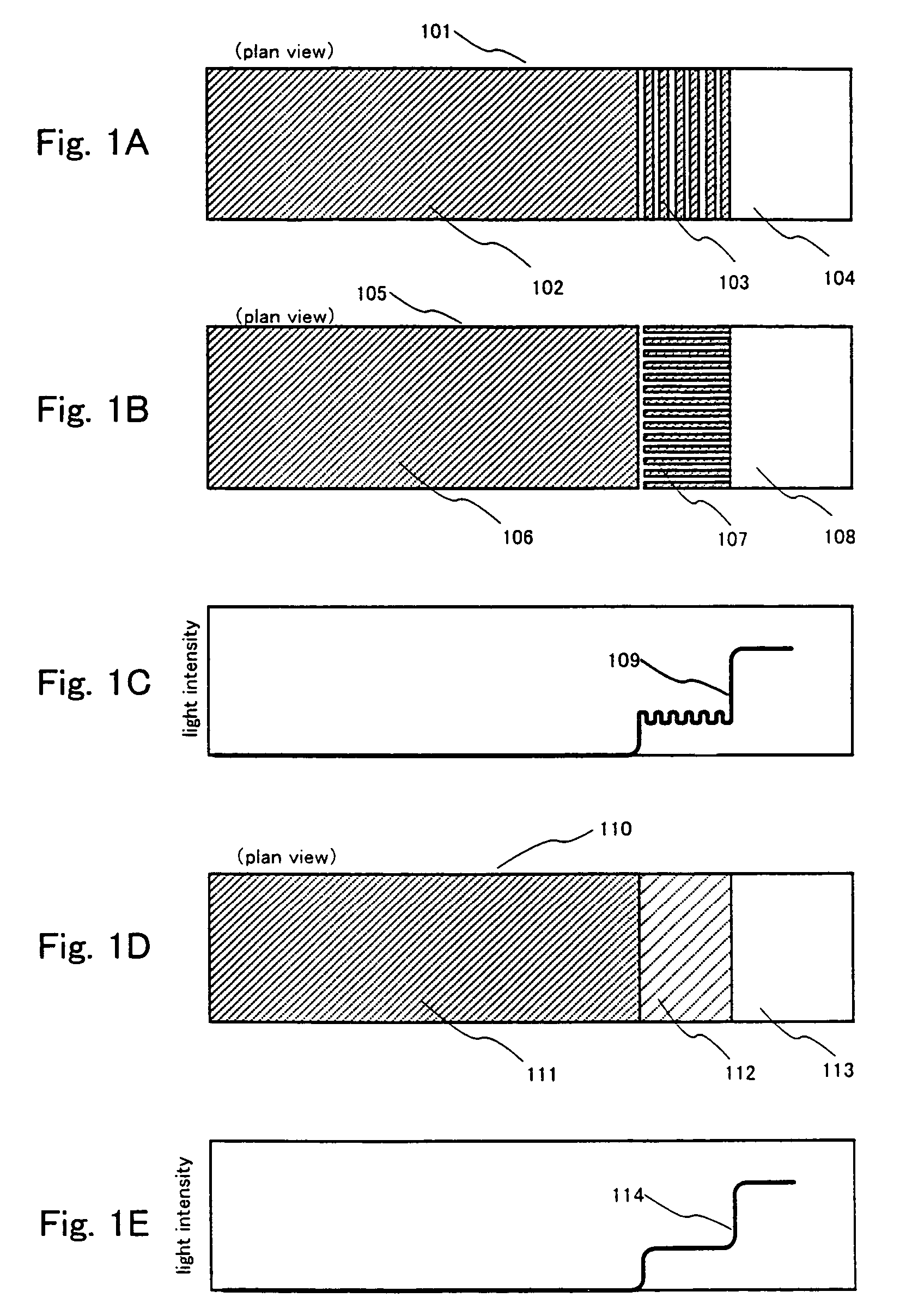
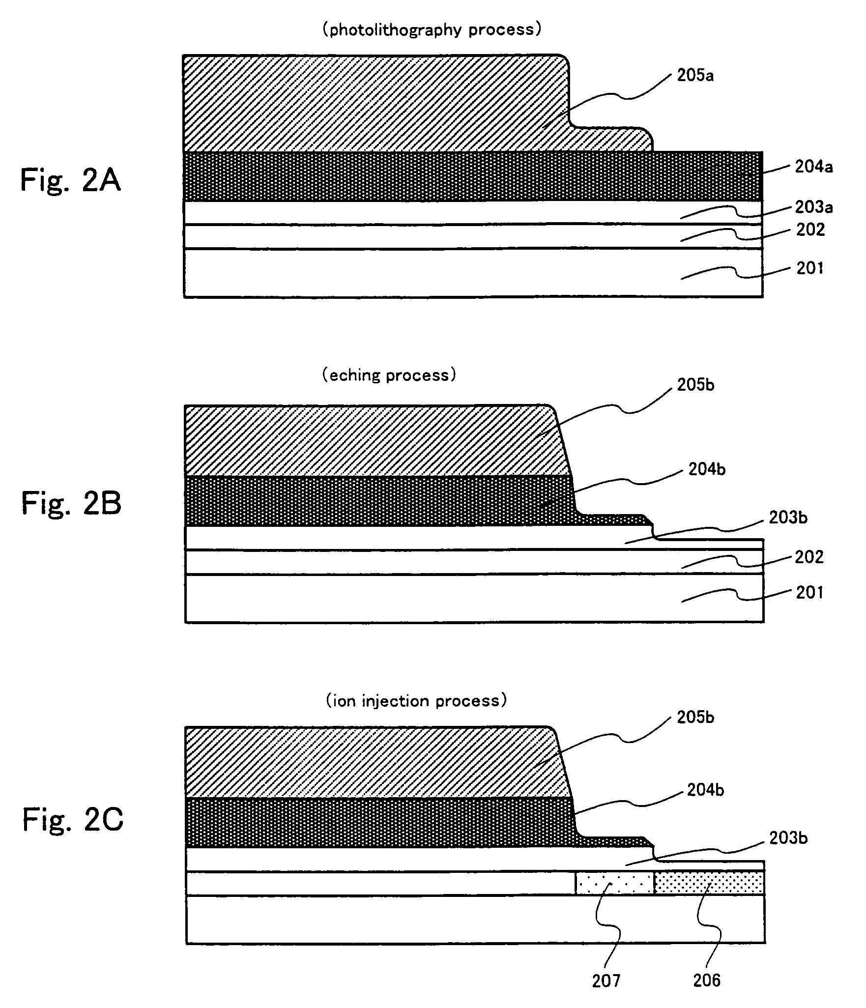
[0092]A case of applying a photolithography process that utilizes a photomask, or a reticle, for forming a gate electrode having a function of reducing the intensity of light and which is made from a diffraction grating pattern or a translucent film, for forming GOLD structure polycrystalline silicon TFT, is stated based on FIGS. 1A to 1E and FIGS. 2A to 2C.

[0093]First, a structure of a photomask, or a reticle, used for forming a gate electrode and in which is set a supplemental pattern made from a diffraction grating pattern, or a translucent film, and which has a function of reducing the intensity of light, is explained using FIGS. 1A to 1E.

[0094]A supplemental pattern having a function of reducing the intensity of light is established in edge portions of one side, or both sides, of a mask pattern in a photomask, or a reticle, used for forming a gate electrode. Examples of a diffraction grating pattern having a slit portion composed of lines and spaces below the...

embodiment mode 2

[Embodiment Mode 2]

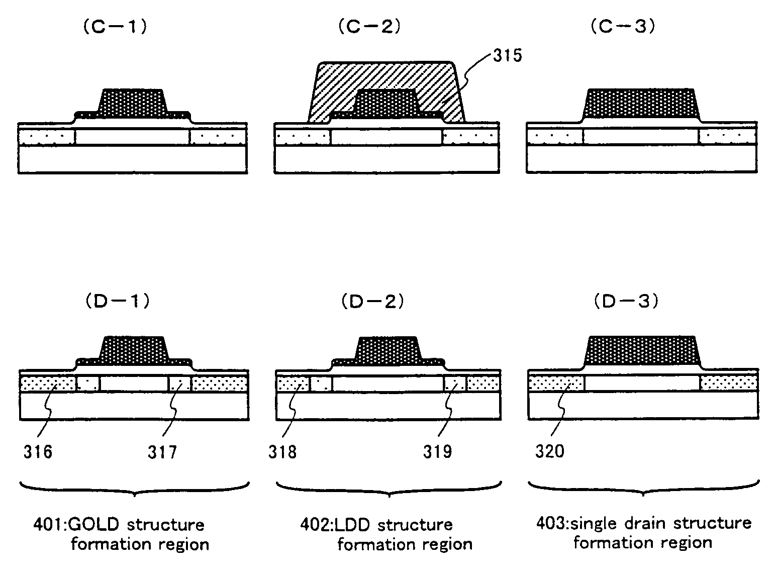
[0104]Various types of circuits are included in a semiconductor device such as a liquid crystal display, and although there are cases in which a GOLD structure having a superior effect against hot carriers is suitable, there are also cases in which an LDD structure having a small off current value are appropriate. Single drain structures may also be suitable, depending upon the circumstances. It is therefore necessary to form GOLD structure, LDD structure, and single drain structure polycrystalline silicon TFTs separately for each circuit. In embodiment mode 2, a method of forming GOLD structure, LDD structure, and single drain structure polycrystalline silicon TFTs separately for each circuit is discussed based upon FIGS. 3A to 3D. Note that the photomasks or reticles 101, 105, and 110 used for forming the gate electrodes (see FIGS. 1A, 1B, and 1D) have already been discussed in embodiment mode 1, and therefore an explanation will be omitted here.

[0105]Concerning...

embodiment mode 3

[Embodiment Mode 3]

[0117]A case in which a photolithography process, utilizing a photomask or a reticle used for forming a gate electrode having a function of reducing the intensity of light and composed of a diffraction grating pattern or a translucent film, is applied to the formation of a GOLD structure polycrystalline silicon TFT, is discussed based on FIGS. 9A to 9E and 10A to 10C. First, a structure of a photomask, or a reticle, used for forming a gate electrode and in which a supplemental pattern made from a diffraction grating pattern, or a translucent film is set, and which has a function of reducing the intensity of light, is explained using FIGS. 9A to 9E.

[0118]A supplemental pattern having a function of reducing the intensity of light is established in edge portions of one side, or both sides, of a mask pattern in a photomask, or a reticle, used for forming a gate electrode such that transmittivity is gradually increased in proportion to distance from mask pattern. Examp...


PUM

PropertyMeasurementUnit
temperatureaaaaaaaaaa
channel lengthaaaaaaaaaa
pressureaaaaaaaaaa

Abstract

Formation of LDD structures and GOLD structures in a semiconductor device is conventionally performed in a self aligning manner with gate electrodes as masks, but there are many cases in which the gate electrodes have two layer structures, and film formation processes and etching processes become complex. Further, in order to perform formation of LDD structures and GOLD structures only by processes such as dry etching, the transistor structures all have the same structure, and it is difficult to form LDD structures, GOLD structures, and single drain structures separately for different circuits. By applying a photolithography process for forming gate electrodes to photomasks or reticles, in which supplemental patterns having a function of reducing the intensity of light and composed of diffraction grating patterns or translucent films, are established, GOLD structure, LDD structure, and single drain structure transistors can be easily manufactured for different circuits through dry etching and ion injection process steps.

Description

CROSS-REFERENCE TO RELATED APPLICATIONS[0001]This application is a continuation application of U.S. application Ser. No. 09 / 925,512, filed Aug. 10, 2001, which claims the benefit of foreign priority applications filed in Japan as Ser. No. 2000-244860 on Aug. 11, 2000 and as Ser. No. 2000-267851 on Sep. 4, 2000. This application claims priority to each of these prior applications, and the disclosures of the prior applications are considered part of (and are incorporated by reference in) the disclosure of this application.BACKGROUND OF THE INVENTION[0002]1. Field of the Invention[0003]The present invention relates to a method of manufacturing a semiconductor device having circuits formed by thin film transistors (hereafter abbreviated as TFTs) and by MOS transistors. As examples of semiconductor devices, there are electro-optical devices structured by TFTs, such as liquid crystal displays and EL (electroluminescence) displays, and LSIs structured by MOS transistors.[0004]2. Descriptio...

Claims


Application Information

Patent Timeline
Patent Type & Authority Patents(United States)
IPC IPC(8): H01L21/84H01L21/3213H01L21/336H01L29/423H01L29/786
CPCH01L21/28114H01L21/32136H01L21/32139H01L27/1214H01L29/42384H01L29/66757H01L29/78621H01L29/78627H01L27/1288H01L29/66598H01L2029/7863Y10S438/949
Inventor OHNUMA, HIDETOUEHARA, ICHIRO
Owner SEMICON ENERGY LAB CO LTD
Why Eureka
Try Eureka