Foam dispenser

a foam dispenser and dispenser technology, applied in the direction of dispensers, liquid transfer devices, holders, etc., can solve the problems of difficult to adjust the ratio of air to liquid, affecting the quality of foam, and affecting the effect of foam quality

Inactive Publication Date: 2005-06-30
DEB IP
View PDF10 Cites 76 Cited by
  • Summary
  • Abstract
  • Description
  • Claims
  • Application Information

AI Technical Summary

Problems solved by technology

The former type of foamer has the disadvantage that the quality of foam varies depending on the dispensing force.
The latter design, although it works very well under most circumstances, has a number of characteristics that in certa

Method used


Image

  • Foam dispenser
  • Foam dispenser
  • Foam dispenser

Examples


Embodiment Construction

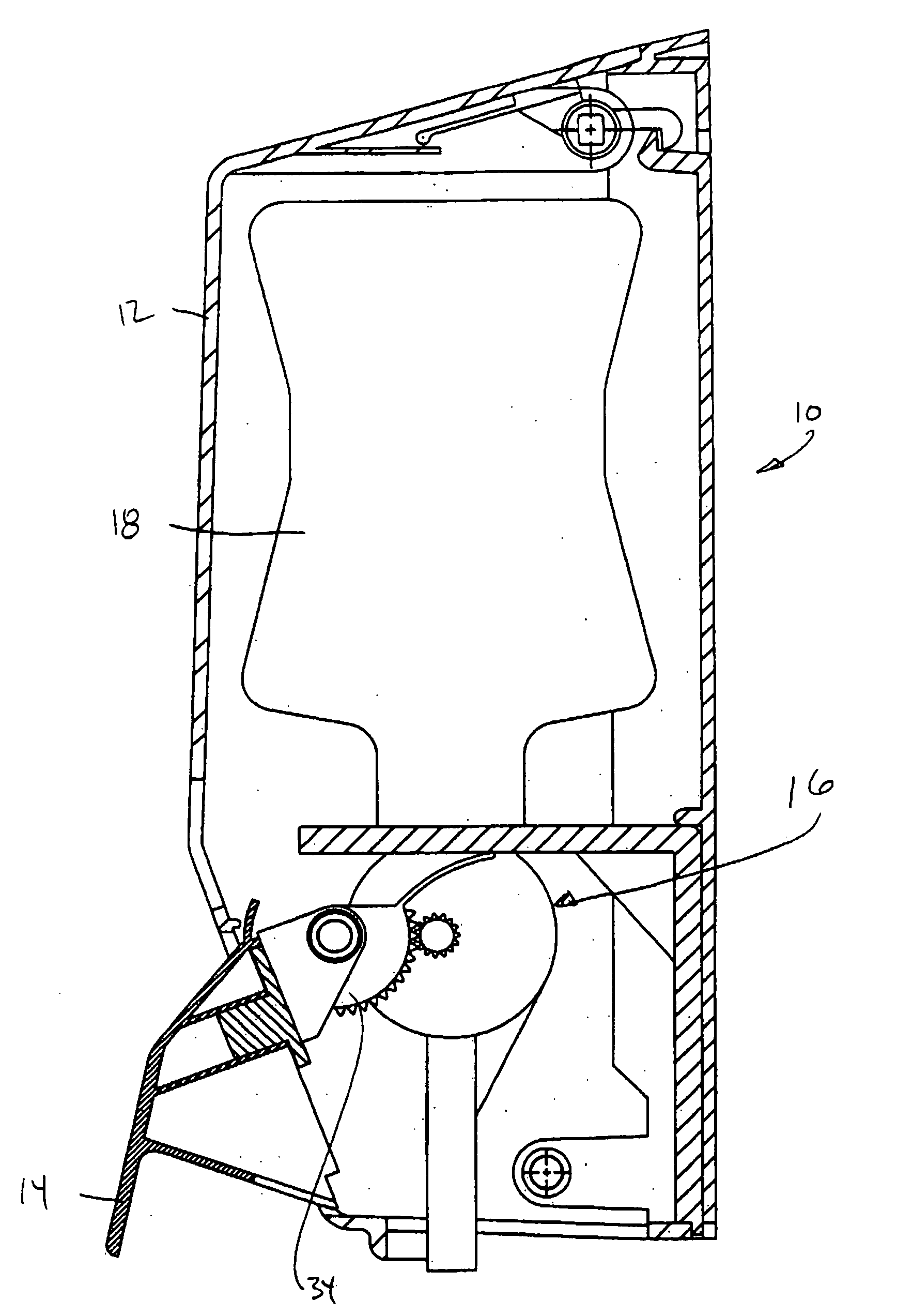
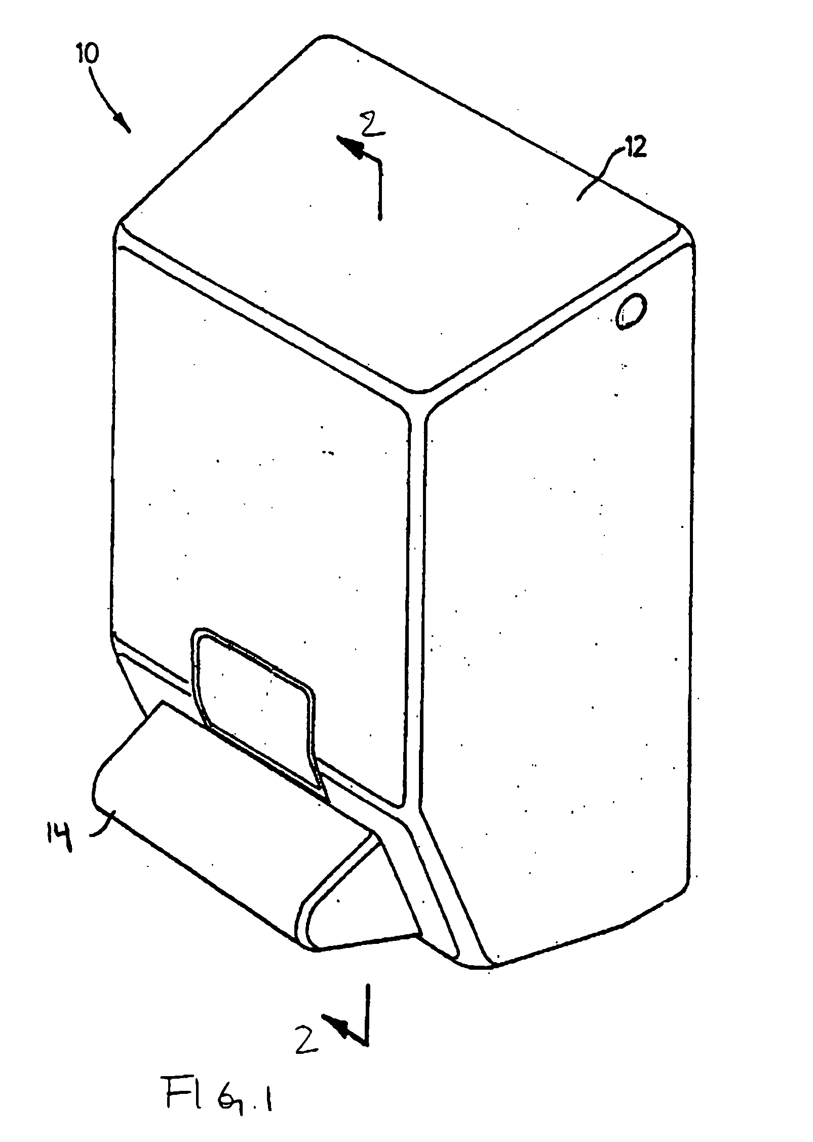
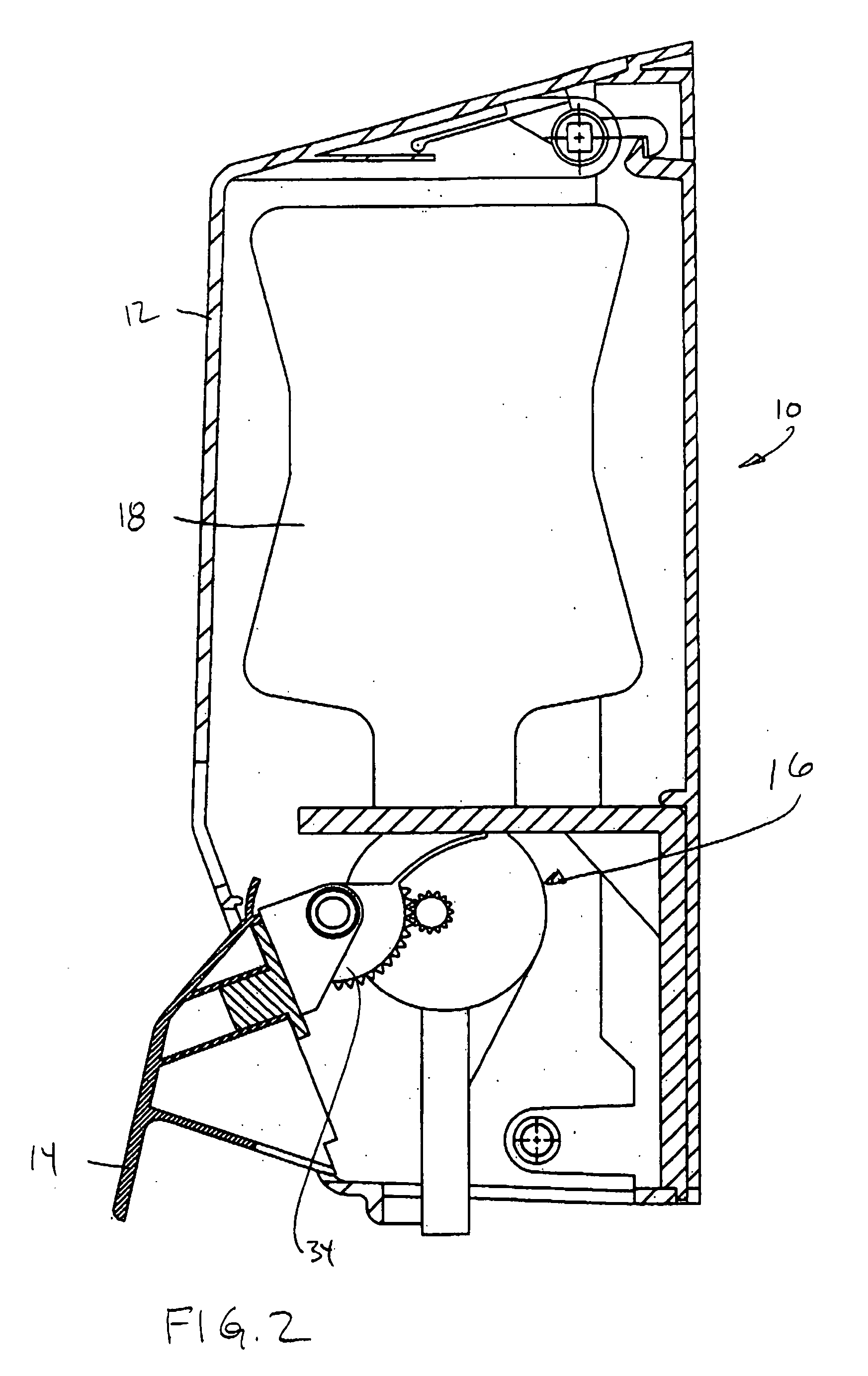
[0015] Referring to FIG. 1 and FIG. 2, a liquid dispenser containing a liquid container and pump is shown generally at 10. Dispenser 10 includes a housing 12 and a drive bar or lever 14. The lever 14 is operably connected to the rotary pump assembly 16 which is connected to a collapsible liquid container 18. The lever 14 is attached to a drive rack 34 which engages the pumps in the rotary pump assembly.

[0016] Referring to FIG. 3, the first embodiment of the rotary pump assembly is a double lobe pump and is shown generally at 20. Double lobe pump 20 includes a soap pump 22 and an air pump 24. The soap pump 22 and the air pump 24 each have a pair of intermeshing tri-lobes 26 and 28, respectively. Each pair of tri-lobes 26, 28 rotate in opposite directions. Each of the soap pump 22 and the air pump 24 have a soap pump housing 30 and an air pump housing 32, respectively. A drive rack 34 is connected to the drive bar or lever 14. The drive rack 34 is operably connected to the lobes 26 a...


PUM


Abstract

A foam dispenser is for use with a container containing soap or other liquid. The device includes a rotary soap pump, a rotary air pump, a mixing chamber, a porous membrane and an actuator or driver. The rotary soap pump has a soap inlet and a soap outlet and the soap inlet is operably connectable to the container. The rotary air pump has an air inlet and an air outlet. The mixing chamber is in flow communication with the air outlet and the soap outlet and the mixing chamber has an outlet. The porous membrane is positioned such that an air and soap mixture that passes through the mixing chamber outlet passes through the porous membrane thereby producing foam. The actuator or driver is operably connected to the rotary soap pump and the rotary air pump.

Description

FIELD OF THE INVENTION [0001] This invention relates to foam dispensers and in particular foam dispensers having a rotary drive mechanism. BACKGROUND OF THE INVENTION [0002] Liquid dispensers for dispensing soap and the like are well known. There are a wide variety of liquid dispensers for use in association with liquid soap. Some of these dispense the soap or other liquid in the form of a foam. There are a number of advantages that are realized by dispensing in the form of foam. Specifically foam is easier to spread than the corresponding liquid. As well there is much less splashing or run-off since the foam has a much higher surface tension than the liquid. In addition, the foam requires much less liquid to produce the same cleansing power as compared to the un-foamed liquid due to the much higher surface area of the foam. Accordingly the cost to wash a specific number of hands is reduced since the amount of soap used is reduced. Similarly there are environmental benefits from usi...

Claims


Application Information

Patent Timeline
IPC IPC(8): A47K5/06A47K5/12A47K5/16B01F3/04B65D25/38B65D47/34B65D83/76B67D7/60B67D7/76
CPCA47K5/16
Inventor MATTHEWS, SHAUN KERRYCREAGHAN, DAVID MICHAEL ROSS
Owner DEB IP
Why Eureka
Try Eureka