Solid state light device

a light device and solid state technology, applied in the direction of fixed installation, lighting and heating equipment, instruments, etc., can solve the problems of system inefficiency and approximately 70% loss of light generated

Inactive Publication Date: 2005-06-30
3M INNOVATIVE PROPERTIES CO
View PDF88 Cites 171 Cited by
  • Summary
  • Abstract
  • Description
  • Claims
  • Application Information

AI Technical Summary

Benefits of technology

[0008] In accordance with a first embodiment of the present invention, photon emitting device comprises a plurality of solid state radiation sources to generate radiation. The solid state radiation sources can be disposed in an array pattern. Optical concentrators, arranged in a corresponding array pattern, receive radiation from corresponding solid state radiat

Problems solved by technology

These present systems are inefficient, with approximately 70% loss of the light generated in some cases.
In multiple fiber systems, these los

Method used


Image

  • Solid state light device
  • Solid state light device
  • Solid state light device

Examples


Embodiment Construction

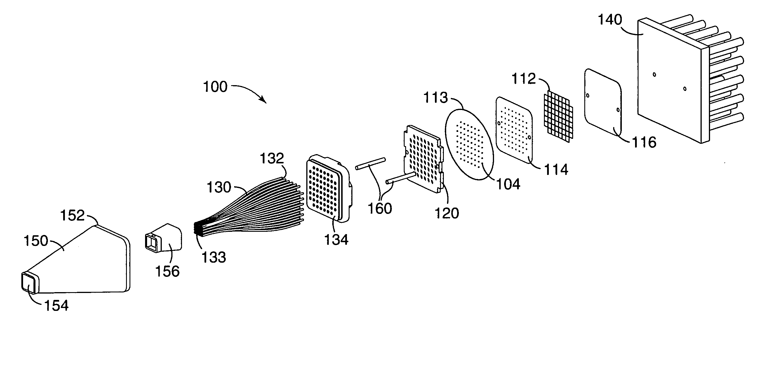
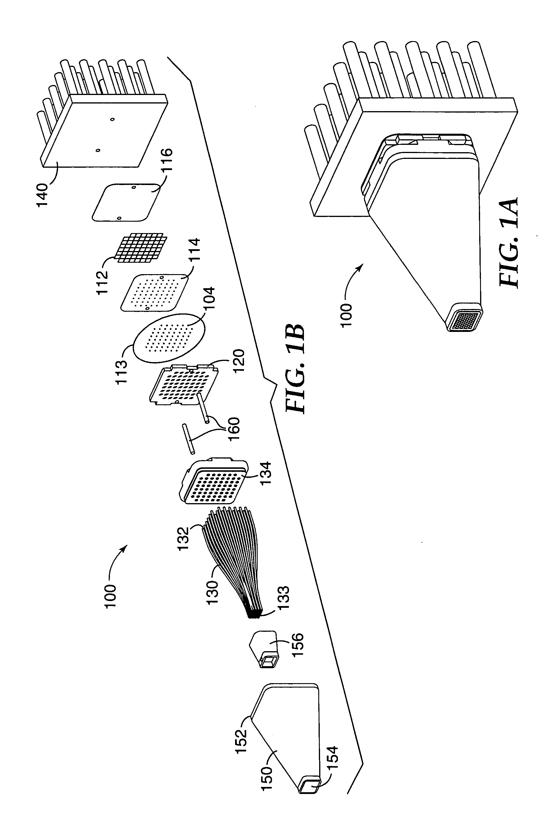
[0028]FIG. 1A shows a solid state light device 100 (also referred to herein as an illumination device or photon emitting device) in an exemplary configuration. Light device 100 is shown in an exploded view in FIG. 1B. By “light” it is meant electromagnetic radiation having a wavelength in the ultraviolet, visible, and / or infrared portion of the electromagnetic spectrum. In the construction described below, the light device 100 can have an overall compact size comparable to that of a conventional High Intensity Discharge (HID) bulb, thus providing a replacement for a discharge lamp device in various applications including road illumination, spot lighting, back lighting, image projection and radiation activated curing.

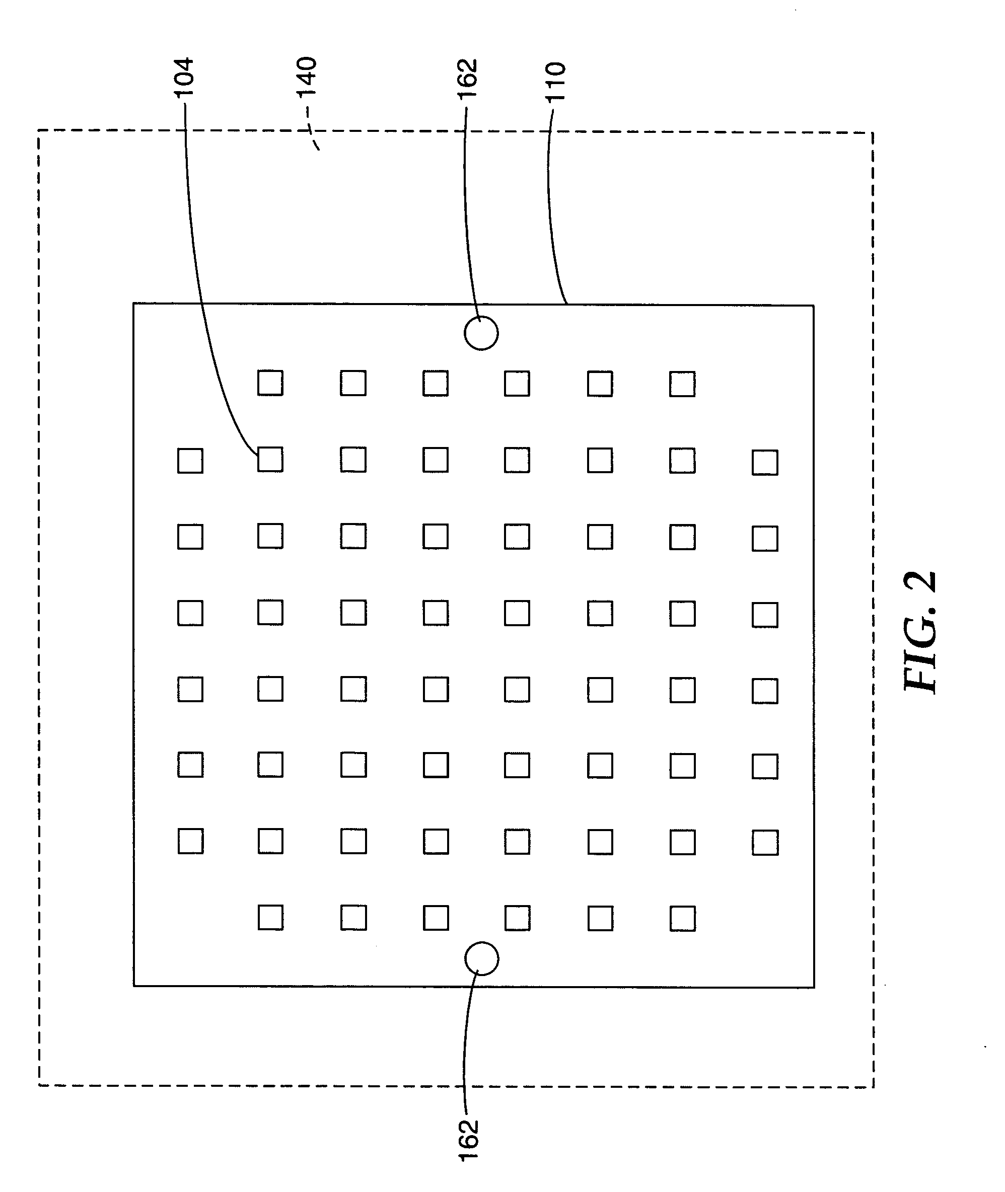
[0029] Light device 100 comprises an array of solid state radiation sources 104 to generate radiation. The radiation is collected and concentrated by a corresponding array of optical concentrators 120. The concentrated radiation is then launched into a corresponding arr...


PUM


Abstract

A photon emitting device comprises a plurality of solid state radiation sources to generate radiation. The solid state radiation sources can be disposed in an array pattern. Optical concentrators, arranged in a corresponding array pattern, receive radiation from corresponding solid state radiation sources. The concentrated radiation is received by a plurality of optical waveguides, also arranged in a corresponding array pattern. Each optical waveguide includes a first end to receive the radiation and a second end to output the radiation. A support structure is provided to stabilize the plurality of optical waveguides between the first and second ends. The photon emitting device can provide a replacement for a discharge lamp device in various applications including road illumination, spot lighting, back lighting, image projection and radiation activated curing.

Description

RELATED APPLICATION [0001] The present application is related to co-owned and concurrently filed U.S. patent application entitled “Illumination System Using a Plurality of Light Sources” Ser. No. ______ (Atty. Docket No. 58130US004), incorporated by reference herein in its entirety. The present application is also related to co-owned and concurrently filed U.S. patent applications entitled “Reflective Light Coupler” Ser. No. ______ (Atty. Docket No. 59121US002); “Multiple LED Source and Method for Assembling Same” Ser. No. ______ (Atty. Docket No. 59376US002); “LED Curing Apparatus and Method” Ser. No. ______ (Atty. Docket No. 59432US002); “Illumination Assembly” Ser. No. ______ (Atty. Docket No. 59333US002), “Phosphor Based Light Sources Having a Polymeric Long Pass Reflector” Ser. No. ______ (Atty. Docket No. 58389US004); and “Phosphor Based Light Sources Having a Non-Planar Long Pass Reflector” Ser. No. ______ (Atty. Docket No. 59416US002), each of which is incorporated by refere...

Claims


Application Information

Patent Timeline
IPC IPC(8): F21K99/00F21S8/10F21S8/12F21V8/00F21V29/00G02B6/04G02B6/06G02B6/36G02B6/42H01L33/00H01L33/32H01L33/50H01L33/56H01L33/60
CPCF21K9/00F21K9/52F21S48/1241F21Y2101/02G02B6/06G02B6/3644F21V29/80G02B6/3672G02B6/368G02B6/4206G02B6/4219G02B6/4249F21V29/20G02B6/3668F21K9/61F21Y2115/10F21S41/24F21V29/70F21V29/00G02B6/00G02B6/42
Inventor HENSON, GORDON D.ALBRECHT, BONNIE WEISKOPFLARSON, DONALD K.SIMBAL, JOHN J.MEIS, MICHAEL A.GRIFFIN, MICHAEL E.BROYLES, BRUCE R.
Owner 3M INNOVATIVE PROPERTIES CO
Why Eureka
Try Eureka