Decoupled stacked bulk acoustic resonator-based band-pass filter

a bandpass filter and acoustic resonator technology, applied in the direction of impedence networks, electrical devices, etc., can solve the problems of steep transition between the pass band and the stop band, insufficient stop band attenuation for some applications, etc., and achieve the effect of large attenuation

Active Publication Date: 2005-06-30
AVAGO TECH INT SALES PTE LTD
View PDF63 Cites 96 Cited by
  • Summary
  • Abstract
  • Description
  • Claims
  • Application Information

AI Technical Summary

Benefits of technology

[0013] Embodiments of a band-pass filter in accordance with the invention have characteristics that approximate the above-described ideal characteristics more closely. In particular, such embodiments combin...

Problems solved by technology

Additionally, in an ideal band-pass filter, the slope of the transition between the pass band and the stop band is steep.
However, the characteristics of the band-pass filter 10 deviate from the above-described ideal characteristics because, after the initial fall, the subsequent rise in the frequency response...

Method used


Image

  • Decoupled stacked bulk acoustic resonator-based band-pass filter
  • Decoupled stacked bulk acoustic resonator-based band-pass filter
  • Decoupled stacked bulk acoustic resonator-based band-pass filter

Examples


Embodiment Construction

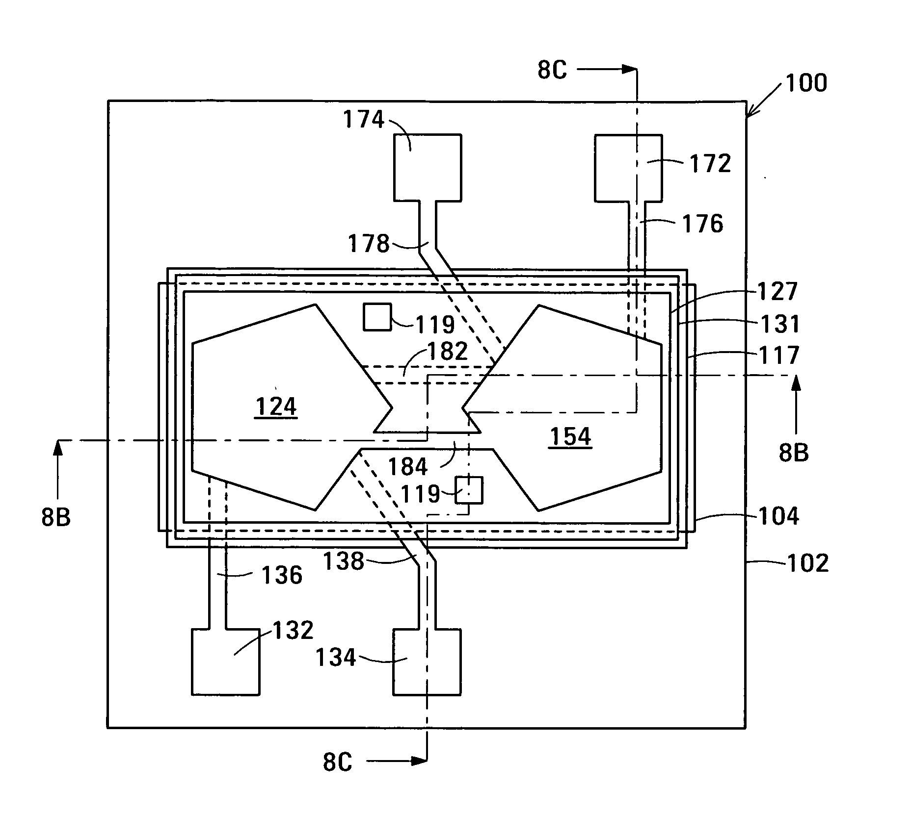
[0029]FIG. 6 is a schematic drawing of a first embodiment 100 of a DSBAR-based band-pass filter in accordance with the invention. Band-pass filter 100 is composed of a first decoupled stacked bulk acoustic resonator (DSBAR) 106 and a second DSBAR 108. Each DSBAR comprises a first film bulk acoustic resonator (FBAR), a second FBAR and an acoustic decoupler between the FBARs. Each FBAR has opposed planar electrodes and a piezoelectric element between the electrodes. Band-pass filter 100 additionally has first terminals 132 and 134, second terminals 172 and 174, and an electrical circuit 140 that connects first DSBAR 106 and second DSBAR 108 in series between first terminals 132, 134 and second terminals 172, 174.

[0030] The embodiment of band-pass filter 100 shown in FIG. 6 has a 1:1 ratio between the impedance between first terminals 132, 134 and the impedance between second terminals 172, 174. Band-pass filter 100 will now be described in further detail with reference to the example...


PUM


Abstract

The band-pass filter has first terminals, second terminals, a first decoupled stacked bulk acoustic resonator (DSBAR), a second DSBAR, and an electrical circuit connecting the first DSBAR and the second DSBAR in series between the first terminals and the second terminals. Each DSBAR has a first film bulk acoustic resonator (FBAR), a second FBAR and an acoustic decoupler between the FBARs. Each FBAR has opposed planar electrodes and a piezoelectric element between the electrodes.

Description

RELATED APPLICATIONS [0001] This application is a Continuation-in-Part of U.S. patent application Ser. No. 10 / 699,289 of John D. Larson III entitled Stacked Bulk Acoustic Resonator Band-Pass Filter with Controllable Pass Bandwidth and of U.S. patent application Ser. No. 10 / 965,541 of John D. Larson III and Stephen Ellis entitled Decoupled Stacked Bulk Acoustic Resonator Band-Pass Filter with Controllable Pass Bandwidth. The applications are both assigned to the assignee of this application and are incorporated by reference.BACKGROUND [0002] Band-pass filters are used in an ever-widening variety of electronic products, especially wireless products. An ideal band-pass filter provides little or no attenuation of signals at frequencies in the pass band, has a flat frequency response in the pass band, and provides a large attenuation of signals at frequencies outside the pass-band. Additionally, in an ideal band-pass filter, the slope of the transition between the pass band and the stop ...

Claims


Application Information

Patent Timeline
IPC IPC(8): H03H9/13H03H9/60
CPCH03H9/132H03H9/605H03H9/587H03H9/584
Inventor LARSON, JOHN D. IIIELLIS, STEPHEN
Owner AVAGO TECH INT SALES PTE LTD
Why Eureka
Try Eureka