Vibration-damped holder for additional handle

a vibration-damped and handle technology, applied in the field of vibration-damped holder for additional handle, can solve the problems of damping means tearing and handle means being destroyed, and achieve the effects of convenient detachment, high strength, and added stability

Active Publication Date: 2009-11-19
AEG ELECTRIC TOOLS
View PDF20 Cites 15 Cited by
  • Summary
  • Abstract
  • Description
  • Claims
  • Application Information

AI Technical Summary

Benefits of technology

[0014]Preferably, the damping means, which may be cylindrical, comprises a cladding, in particular a multi-part cladding, which cladding preferably comprises a ring-shaped envelope, preferably a metal ring. Such a cladding is for example particularly well-suited to serve as stopper element for the damping means. The damping means, in particular those parts cooperating with the elastic element, may abut on the cladding in an initial (basic) state which does not need to absorb any application of force by dynamic deformation of the elastic element. Thus, the cladding preferably surrounds the parts cooperating with the elastic element so that these are held in the cladding when the elastic element fails, for example when it tears off or breaks. Thus, one can prevent that the handle element is unintentionally released from the power tool in which the damper is mounted. A ring-shaped envelope of the cladding is intended for additional stability which is provided in special measure by a metal ring. A robust cladding not only serves to protect the elastic element which may be received in the cladding, but also has an especially high strength which can be of particular relevance in a use of the cladding as stopper element.
[0015]Advantageously, the damper further comprises an attachment means for attaching the damper to the power tool, which is in particular provided with a clamping means. An attachment means on the side of the damper has the advantage that the damper may be used with a plurality of power tools. Thus, it is also possible to subsequently equip a power tool with the inventive damper without problems. Moreover, in the advantageous configuration of the attachment means as clamping means no thread or the like on the electric tool is necessary. Rather, the damper can be clamped directly onto the housing of the electric tool and is, thus, also particularly easy to detach again, for example for transport. Apart from that, the attachment means may be formed by a screw thread which can be screwed into the housing of the electric tool.
[0016]A handle according to the invention for a power tool having an axis of vibration comprises a damper which can be configured as described above, and a handle means connected with the damper. Together with the handle means, the damper forms a handle for a power tool, by means of which the power tool may be guided and which attenuates vibrations of the power tool arising along an axis of vibration particularly well. Advantageously, the handle is characterized in that the damping means, the distancing means and the handle means, in particular in this order, are arranged linearly one after the other. The damping means, the distancing means and the handle means are, thus, arranged in succession one after the other so that the ratio of the distances between the handle means and the axis of vibration of a power tool to which the handle is attached and the distance between the damping means and the axis of vibration can be adjusted particularly well. The damping means is thus situated between the handle means and the axis of vibration, and the distancing means is situated between the damping means and the handle means, whereby the distance between the damping means and the handle means can be adjusted so that the desired ratio of the distances between the handle means and the axis of vibration, and the damping means and the axis of vibration may be maintained.
[0018]A power tool according to the invention having an axis of vibration, in particular a drill or an impact drill or a hammer drill, is characterized in that it comprises the above-described handle. Such a power tool features a particularly good vibration damping of the vibrations arising along the axis of vibration. The power tool thus complies with particularly high demands in occupational health and allows a continuous use of the power tool without having to fear damages to the health of the user.

Problems solved by technology

Such elements are advantageous because the damping means may show symptoms of fatigue during its operation, which in an extreme case may lead to the destruction of the damping means and possibly the tearing-off of the handle means.

Method used


Image

  • Vibration-damped holder for additional handle
  • Vibration-damped holder for additional handle
  • Vibration-damped holder for additional handle

Examples


Embodiment Construction

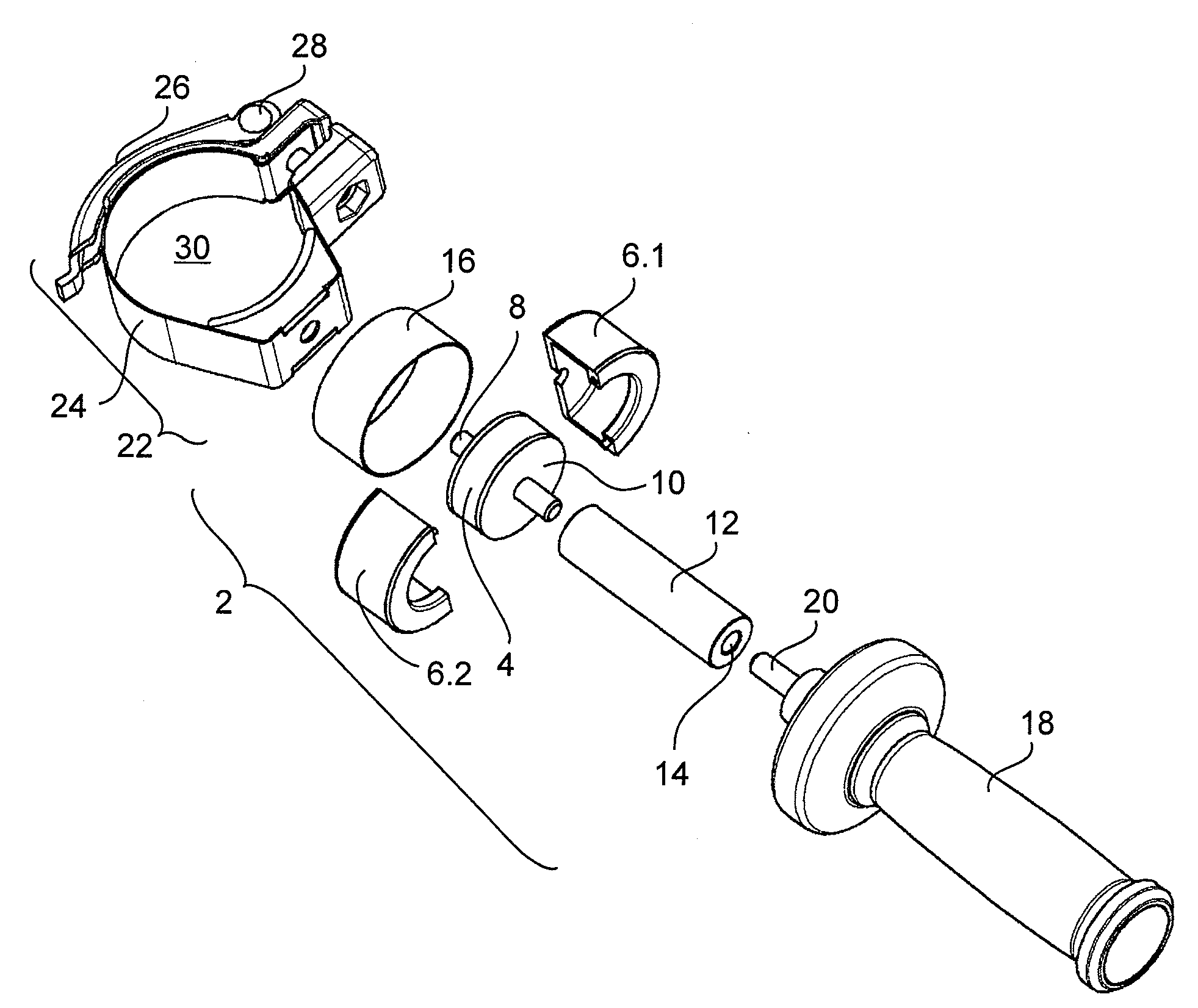
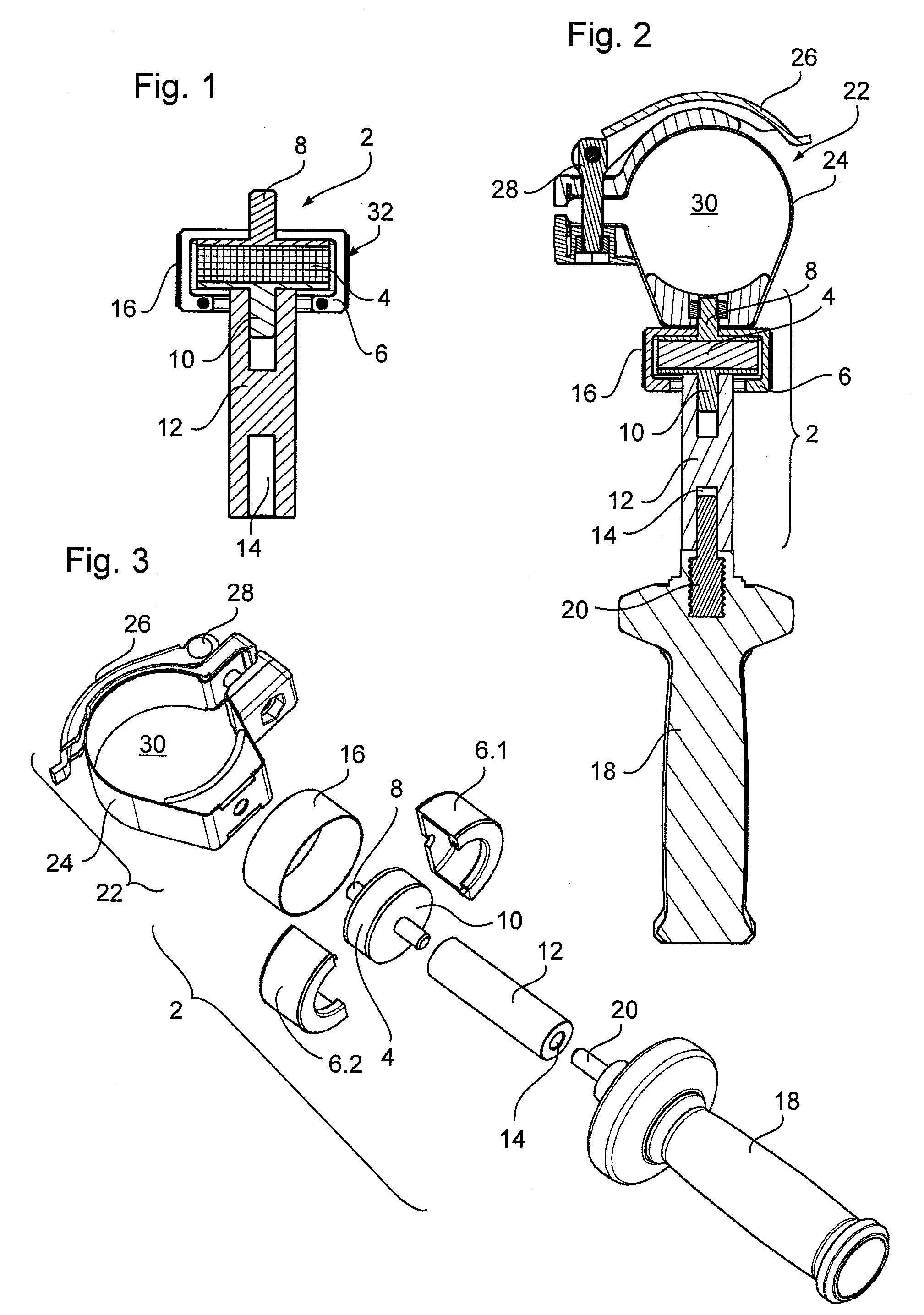
[0025]FIG. 1 shows a sectional view of a damper 2 having a damping means, such as a damping arrangement 32, and a distancing means, such as a spacer 12. The section through the damper 2, which has a generally cylindrical form, is substantially taken along the cylinder axis of the damper 2. In the upper part of the figure there is a damping means 32 which has an elastic element 4, a first connecting element 8 and a second connecting element 10 in a two-part cladding 6. The cladding forms a cylinder having a first diameter in which the elastic element 4 shown in FIG. 1 is also formed cylindrically and is inserted therein. In this exemplary embodiment, the elastic element 4 is formed of NBR (nitrile rubber), wherein the elastic element 4 may also be formed of other elastic materials, a coil spring or the like.

[0026]One of the connecting elements 8, 10 is respectively attached to the upper and lower front faces of the cylindrical elastic element 4. The first connecting element 8, which ...


PUM


Abstract

A damper for mounting between a power tool, having an axis of vibration, and a handle. The damper includes a damping arrangement for damping impacts and a spacer. The spacer is dimensioned so that, when the damper is mounted to the power tool, a ratio of a first distance between the axis of vibration and the handle to a second distance between the axis of vibration and the damping arrangement is at least 2:1. Further, a handle having such a damper for a power tool, as well as the corresponding power tool having such a handle, are described.

Description

REFERENCE TO RELATED APPLICATIONS[0001]This application is related to, and claims priority from, European Patent Application No. 08 009 186.1, filed May 19, 2008, entitled “VIBRATION-DAMPED HOLDER FOR ADDITIONAL HANDLE,” the entirety of which is incorporated by reference herein and made a part of the present specification.BACKGROUND OF THE INVENTION[0002]1. Field of the Invention[0003]The invention relates to a damper for mounting between a power tool having an axis of vibration, on the one hand, and a handle device for the power tool, on the other hand, wherein the damper comprises a damping means for damping impacts (absorbing shocks) and a distancing means. The invention further relates to a handle for a power tool having an axis of vibration and to a power tool having an axis of vibration, in particular a drill or impact drill or a hammer drill.[0004]2. Description of the Related Art[0005]Hand-operated machine tools such as power tools, for example angle grinders or power cutter...

Claims


Application Information

Patent Timeline
Patent Type & Authority Applications(United States)
IPC IPC(8): B25D17/24B25D17/04
CPCB25F5/026B25F5/006
Inventor OESTERLE, MARKUSROBIEU, THOMAS
Owner AEG ELECTRIC TOOLS
Why Eureka
Try Eureka