Apparatus with a rotationally driven body in a fluid-filled housing

a fluid-filled housing, rotating body technology, applied in mechanical apparatus, x-ray tubes, sliding contact bearings, etc., can solve the problems of reducing the efficiency of the cooling device, the inability to implement additional centrifugal forces, and the loss of the coolant that is put into rotation, so as to achieve the effect of low loss

Active Publication Date: 2006-04-11
SIEMENS HEALTHCARE GMBH
View PDF6 Cites 16 Cited by
  • Summary
  • Abstract
  • Description
  • Claims
  • Application Information

AI Technical Summary

Benefits of technology

[0010]An object of the present invention is to provide an apparatus with a rotational body that is rotatably supported is a fluid-filled housing which enables exploitation of the rotational power with particularly low loss. A further object of the invention is to provide an improved rotating piston radiator, i.e., an X-ray radiator having a cathode and anode that are mounted in a vacuum tube in a spatially fixed manner in relation to the tube, the vacuum tube being rotatably supported in a coolant housing, and having a stationary deflection system for lateral deflection of an electron beam directed from the cathode to the anode being provided.
[0014]Due to the rotational directing body between the rotational body and the housing rotating at an intermediate rotational frequency in accordance with the invention, the liquid located in the housing is separated into a region between the rotational body and the rotational directing body and a region between the rotational directing body and the housing. The lost power that occurs in each of the two fluid regions is now determined by the relative frequency of the rotational body with respect to the rotational directing body, or the relative frequency of the rotational directing body with respect to the housing. As a result of the super-proportional dependency of the rotational power on the relative frequency, the total of the power losses occurring in the two liquid regions is less than the power loss that would occur without the rotational directing body for the same rotational frequency of the rotational body with respect to the housing. The net rotational power thus is reduced considerably by the rotational directing body. The use of the rotational directing body represents a simple way in terms of design to reduce the rotational power. A particular advantage to that is no sealed bearings are required.
[0016]The rotational directing body can have a tube-shaped casing enclosing the exterior of the rotational body at a distance therefrom. As used herein, a body is designated as “tube-shaped” that is rotationally symmetrical and hollow, particularly having thin walls. Here, the casing can have a diameter that is constant or varying in the axial direction. In this manner, the liquid regions arranged in the radial direction on the near side and far side of the rotational directing body are fully separated from one another, which prevents a loss-promoting exchange of liquid between these regions.
[0020]The apparatus is in particular an X-ray radiator. Here, the rotational directing body preferably contains at least in one subregion, a radiation protection material, i.e., a material that greatly attenuates X-ray radiation, particularly lead. In this manner, a particularly compact implementation of the X-ray radiator is achieved that guarantees good protection against undesired radiation escape at the same time.
[0021]Among the benefits achieved with the invention are that in a rotating piston radiator, the rotational power is significantly reduced, and simultaneously during rotation of the vacuum tube a turbulent coolant flow is produced that causes efficient cooling by flowing around the anode.

Problems solved by technology

A disadvantage of this known X-ray radiator is the friction losses of the coolant that is put into rotation as the vacuum tube rotates.
A coolant container that rotates along with the vacuum tube, however, can be implemented only in a comparatively expensive manner, particularly since it must be provided with sealed bearings.
Moreover, there is a disadvantage that, due to the rotating coolant housing, additional centrifugal forces arise which can counteract a fast rotation of the vacuum tube.
An undesired friction loss of the described type occurs in every rotational body driven in a fluid bath.

Method used


Image

  • Apparatus with a rotationally driven body in a fluid-filled housing
  • Apparatus with a rotationally driven body in a fluid-filled housing
  • Apparatus with a rotationally driven body in a fluid-filled housing

Examples


Embodiment Construction

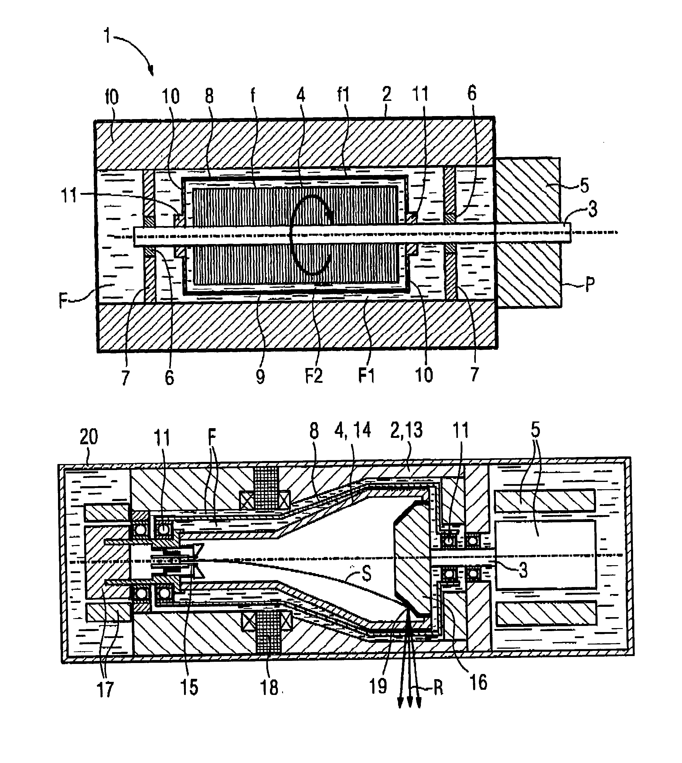
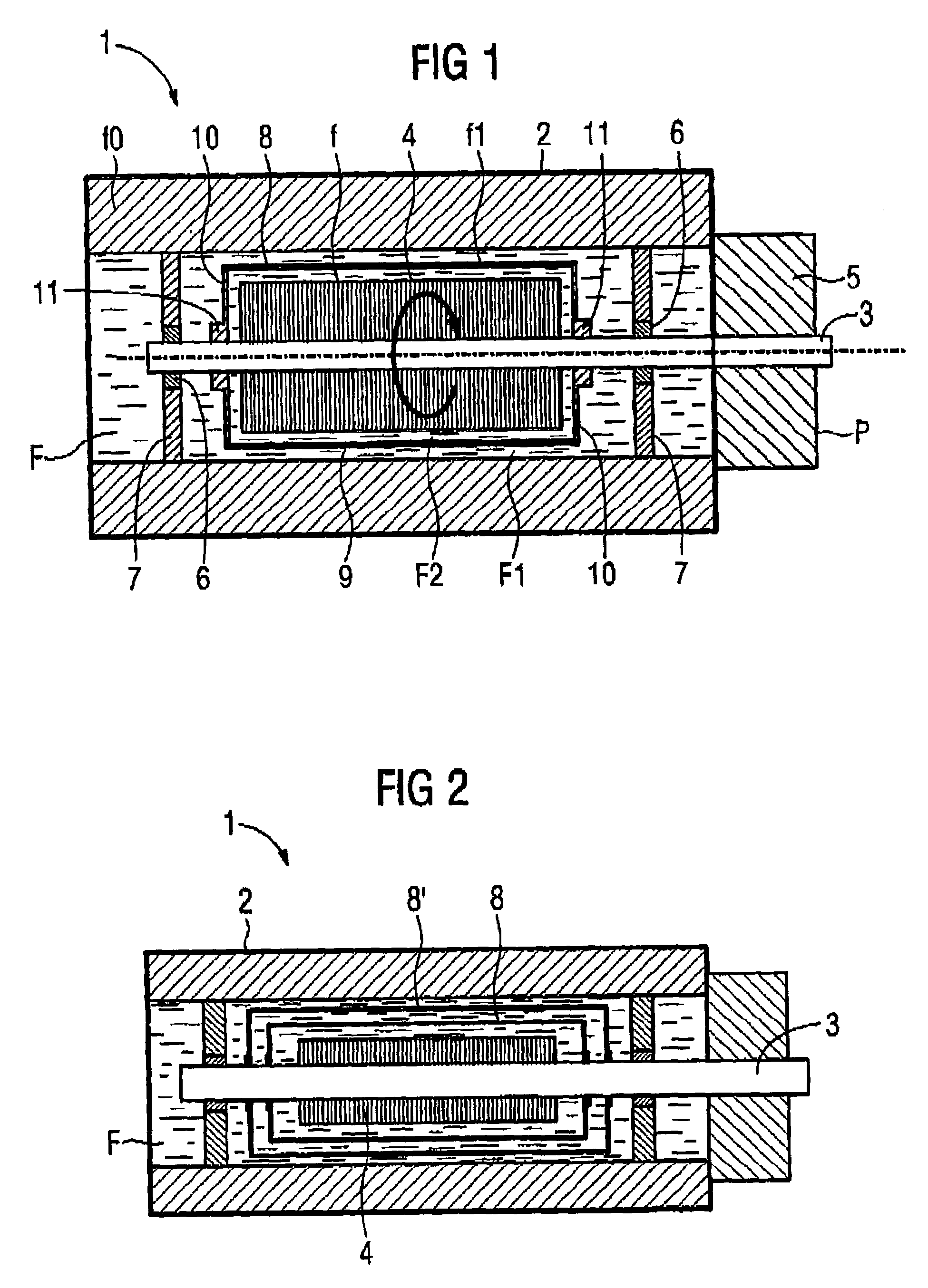
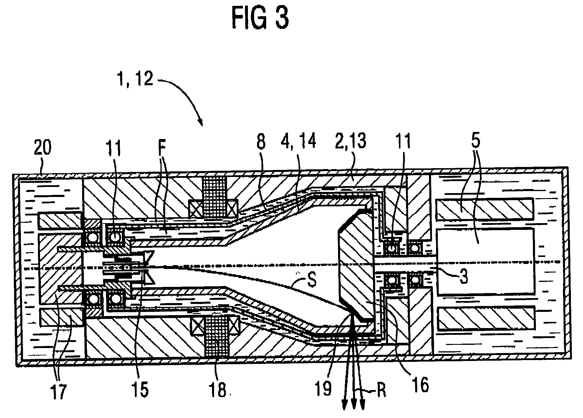
[0025]The apparatus 1 shown in FIG. 1 in a schematic representation includes a stationary housing 2 filled with a fluid F in which housing 2 a rotational body 4 that is rotatable about an axis 3 is supported. The rotational body 4 in the embodiment is rotationally driven by a drive 5, particularly an electric motor. The axis 3 is suspended in the axial direction on both sides of the rotational body 4 on bearings 6, e.g., rolling bearings, within the housing 2. Each bearing 6 is supported by an end plate 7 fixed on the housing 2.

[0026]The apparatus 1 includes, moreover, a rotational directing body 8 with a thin-walled, tube-shaped casing 9 that is disposed concentrically with respect to the rotational body 4 and surrounds it at a radial spacing. This radial spacing is small with respect to the radius of the rotational body 4. In other words, the rotational body 4 and the rotational directing body 8 have only slightly different radii. The rotational directing body 8 is provided on eac...


PUM


Abstract

To reduce the rotational power, an apparatus with a rotational body that is rotationally driven in a fluid-filled housing a rotational directing body is provided between the rotational body and the housing, which is rotatably supported coaxially with respect to the rotational body. The rotational directing body is configured such that in operation it rotates at an intermediate rotational frequency in comparison to the housing and the rotational body. The apparatus is particularly an X-ray radiator having a cathode and anode that are mounted in a vacuum tube in a spatially fixed manner in relation to the tube, the vacuum tube being rotationally driven as a rotational body in a coolant housing.

Description

BACKGROUND OF THE INVENTION[0001]1. Field of the Invention[0002]The present invention relates to an apparatus with a rotational body that is rotationally driven in a fluid-filled housing. The invention relates especially to an X-ray radiator of the type having a cathode and anode that are mounted in a vacuum tube in a spatially fixed manner in relation to the vacuum tube, the vacuum tube being rotatably supported as a rotational body in a coolant housing, and having a stationary deflection system for lateral deflection of an electron beam directed from the cathode to the anode. An X-ray radiator of this type is normally designated as a “rotating piston radiator”.[0003]2. Description of the Prior Art[0004]X-ray radiation is normally generated by striking an anode with an electron beam emanating from a cathode. The cathode and the anode are mounted in a vacuum tube. Normally, an X-ray radiator is equipped nowadays with an anode that rotates under the incident electron beam in order to...

Claims


Application Information

Patent Timeline
Patent Type & Authority Patents(United States)
IPC IPC(8): H01J35/12F16C17/26H01J35/10H01J35/24H01J35/26H01J35/28H01J35/30
CPCH01J35/101H01J35/106H01J35/305H01J2235/1208H01J2235/1046H01J35/1024
Inventor FREUDENBERGER, JORGSCHARDT, PETER
Owner SIEMENS HEALTHCARE GMBH
Why Eureka
Try Eureka