[0014] The aim is to significantly reduce the lateral construction space of a cover, thereby however effecting a significantly smaller-shell volume. But since only a restricted shell volume will therefore be available in comparison with known shells of semispherical or domed design having considerable width and outward curvature, the actual attenuation effect however depending particularly on a large encapsulated volume in the case of a known hearing protection, provision must be made for means which ensure adequate sound attenuation in
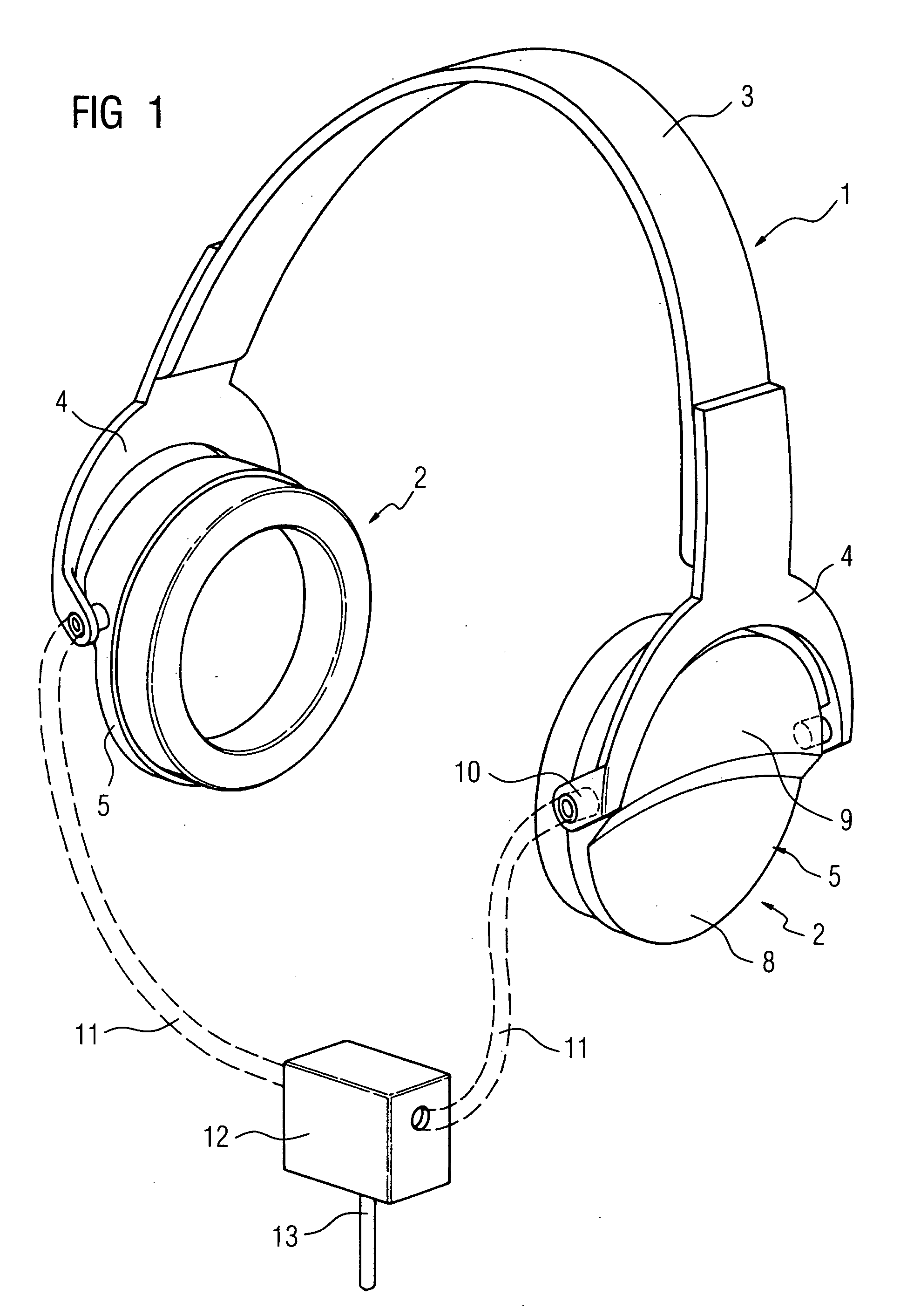
spite of limited volume and limited lateral structure of the outer shell. In order to achieve this, the invention provides for an inner part which is arranged in and permanently connected to the plastic outer shell, said inner part consisting of a dimensionally stable plastic
mass and essentially filling the outer shell completely. Therefore the outer shell can be either completely filled by the inner part as far as the shell edge, or merely filled to a large extent, wherein e.g. an offset or an edge section facing the ear might remain clear and serve to include a cover, for example. The plastic inner part, whose surface which contacts the outer shell preferably corresponds to the inner
surface contour of the outer shell such that it can be positively inserted in a custom-fit manner, is a heavy compact plastic element which should be embodied as densely as possible, if possible from a
solid material or including a minimal amount of aerating agent during the manufacturing process of the inner part, primarily by
coating or injection molding, in order to achieve a minimal pore volume or a maximal density and weight. In accordance with the invention, it has been shown that an excellent attenuation effect can be achieved if the shell volume is filled by a pure
mass element of this type. As a result of this total mass which—apart from an ear pad which is obviously also provided in the claimed hearing protection—is arranged directly adjacent to the ear of the patient, an excellent attenuation becomes possible since the approaching sound
waves can barely penetrate the “mass block”. In accordance with the invention, the attenuation is therefore achieved by means of a mass block instead of a large volume.
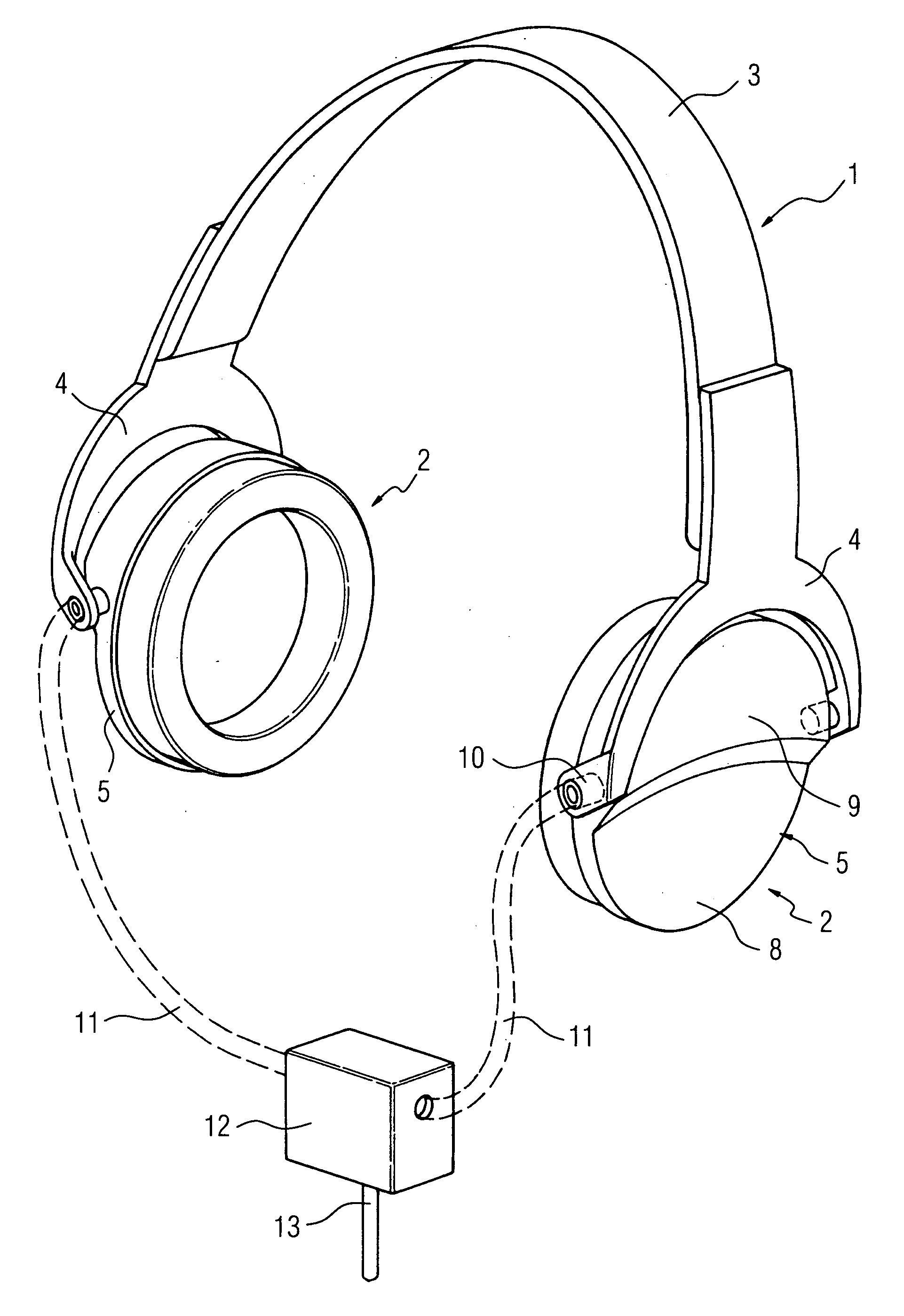
[0016] Since positioning difficulties arise when using a head-neck coil in particular, it is effective and adequate in the case of most applications if, in a completely new type of structural shape, the outer shell has a lower section which is very narrow when viewed from the front and essentially plane when viewed from the side, and which can readily be overlapped by the head-neck coil that extends in the area between the ears and the neck. Adjoining this is an upper section which is wider—viewed from the front—and close to the clip, but is likewise dimensioned such that it can readily be integrated in a normal head coil that surrounds the whole head. This means that the space which is normally available in the upper area is utilized by means of the wider upper section into which more mass can be fitted.
[0018] In particular, in order to allow
welding together or encapsulation of the two parts, it is advantageous if the outer shell and the inner part are made of the same plastic. In the case of
welding, use can be made of a
solvent which dissolves the contacting surfaces of the inner part and the outer shell in such a way that they can intimately bond together. Encapsulation is also readily possible in this case.
[0021] It is frequently desirable to be able to offer music or other entertainment as a diversion for the patient, primarily for relaxation or even to prevent
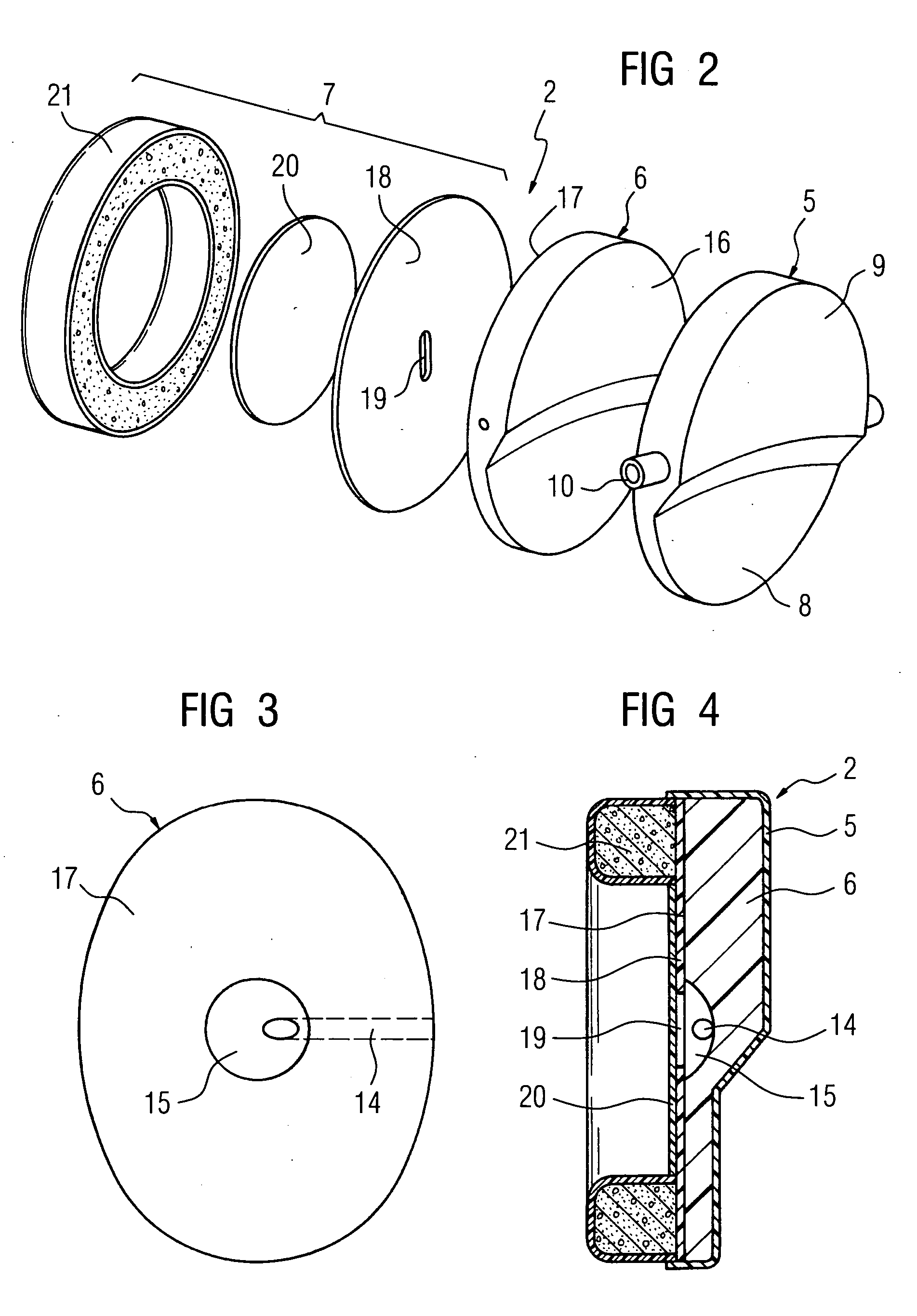
claustrophobia during the MR examination. Furthermore, it is frequently necessary during the examination to be able to give the patient instructions in respect of specific activities to be performed by the patient (e.g. inhale, exhale, hold breath, etc.). Therefore there must be a means of communicating with the patient. In order to achieve this, the invention provides for a connector for an acoustic tube at—viewed from the front—the front or rear end face of the outer shell, said connector being connected to a duct which passes through the inner part and leads to the inner part surface that faces the ear of the examination patient. The positioning of the acoustic tube connector at the front or rear end face in accordance with the invention allows a simple tube management even if coils are in place.
[0022] In this case, it is particularly effective if one of the pivot pins, which project at the front and rear end face, is hollow and forms the connector. This means that one of the pivot pins has a
dual function, serving both as a hinge support for the holding fork and as an acoustic tube connector which can most easily be pushed into and clamped to the hollow pivot pin that is open to the exterior. The pivot pin leads to a duct which passes through the inner part in such a way that the patient can readily be exposed to sound. The duct itself preferably leads to a cavity in the surface of the inner part, said cavity being funnel-shaped, thereby producing a sound funnel via which the sound
waves which are supplied via the tube can spread and be supplied to the ear of the patient.
[0023] Although it is already possible to achieve a relatively good
clarity of the acoustic information in this way, a particularly advantageous configuration of the invention provides for the
insertion of a
vibrating membrane which is opposite the duct opening or the cavity and exposed to the ear of the examination patient. This
vibrating membrane, which is preferably a
plastic film, is made to vibrate by the approaching sound
waves and communicates this into the volume behind it. In this way, the
sound pressure which is produced by the air column in the acoustic tube can be amplified and converted even more effectively, such that the perceptibility of the supplied acoustic information is even better. The
vibrating membrane is preferably arranged on the ear pad which is permanently connected to the inner part. The ear pad itself preferably has a stable mounting which has a perforation, wherein said perforation corresponds to the duct opening or the cavity and is covered by the vibrating membrane that is connected to the mounting. By utilizing this mounting, not only is adequate stability provided for the ear pad, but the ear pad itself can also be cleaned effectively after use, since a surface is provided which is closed to the opening or the duct. The vibrating membrane can also be readily positioned and fixed in this way. In order to attach the ear pad to the inner part, it is suitably adhered firmly to the inner part via the mounting.

