Filter device

Active Publication Date: 2015-05-21
MURATA MFG CO LTD
View PDF1 Cites 14 Cited by
  • Summary
  • Abstract
  • Description
  • Claims
  • Application Information

AI Technical Summary

Benefits of technology

[0006]Preferred embodiments of the present invention provide a

Problems solved by technology

In recent years, the demand for further decreases in the si

Method used


Image

  • Filter device
  • Filter device
  • Filter device

Examples


Embodiment Construction

[0024]Hereafter, various non-limiting examples of preferred embodiments of the present invention will be described. However the following preferred embodiments are merely illustrative examples. The present invention is in no way limited to the following preferred embodiments.

[0025]In addition, in the drawings referred to in the descriptions of preferred embodiments and so forth, members having the same or substantially the same functions are referred to using the same symbols. In addition, the drawings referred to in the descriptions of preferred embodiments and so forth are schematic drawings. The dimensional ratios and so forth of bodies drawn in the drawings may differ from the actual dimensional ratios and so forth of the bodies.

[0026]The dimensional ratios and so forth of bodies may also differ from drawing to drawing. The specific dimensional ratios and so forth of bodies should be determined by referring to the following description.

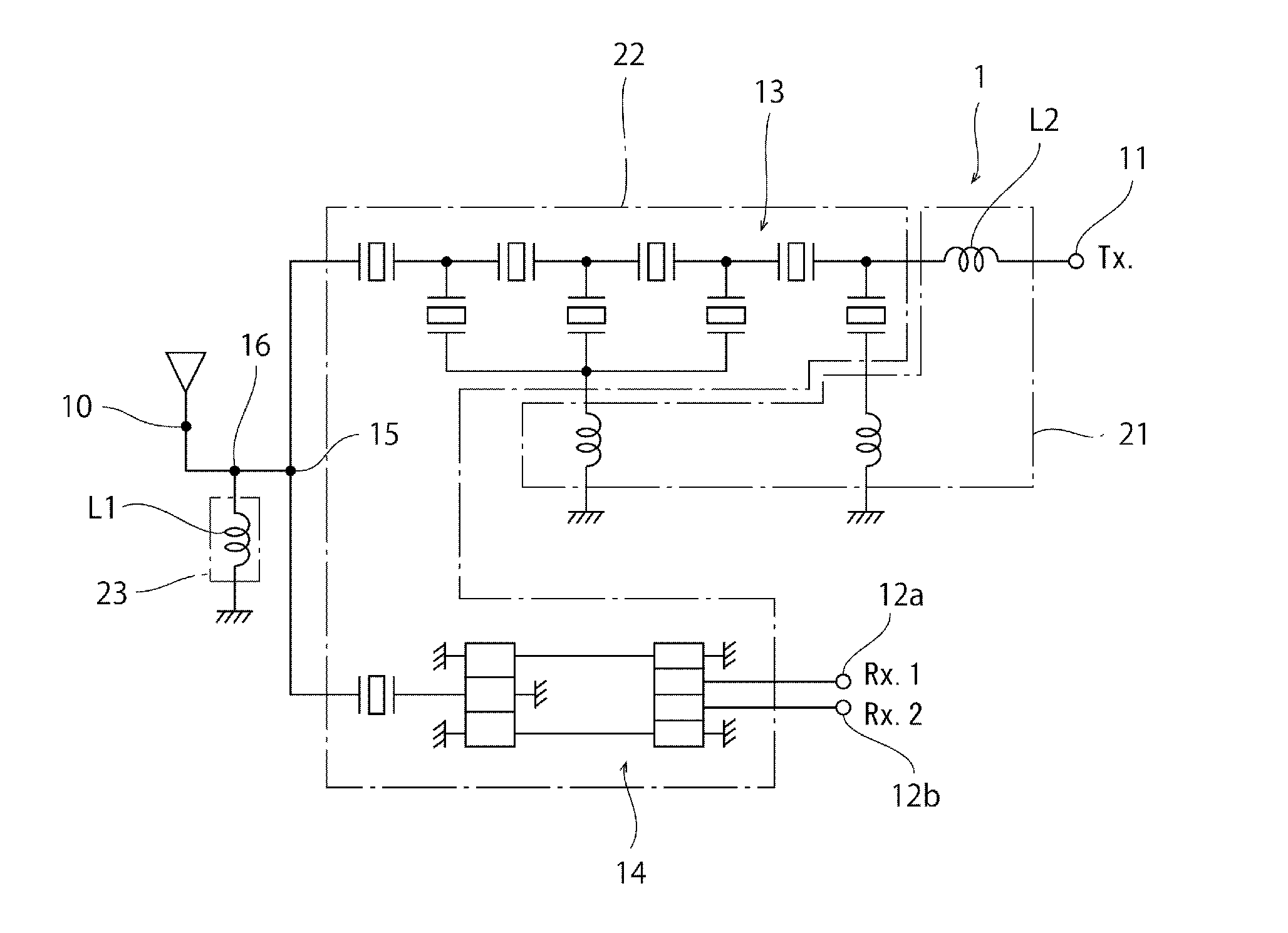
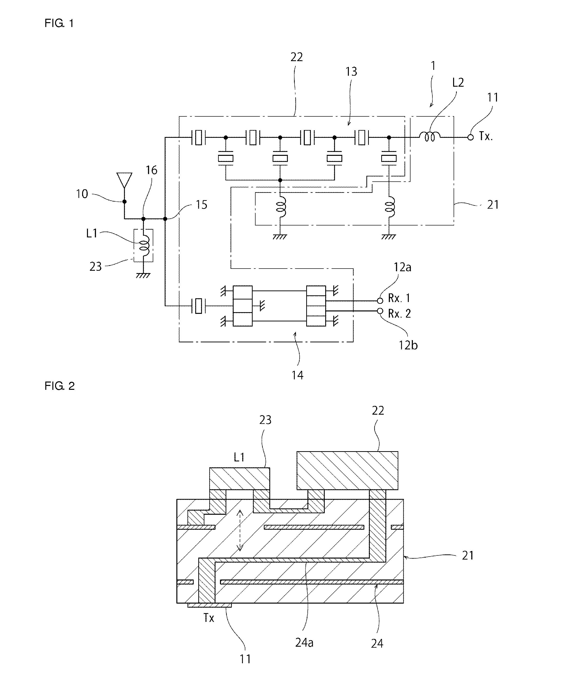
[0027]FIG. 1 is a schematic equivalent circ...


PUM


Abstract

A filter device includes a first signal terminal, a second signal terminal, a filter unit, a first inductor and a second inductor. The filter unit is connected between the first signal terminal and the second signal terminal. The first inductor is connected between a connection point between the filter unit and the first signal terminal, and a ground potential. The second inductor is connected between the filter unit and the second signal terminal. The second inductor is electromagnetically coupled with the first inductor.

Description

BACKGROUND OF THE INVENTION[0001]1. Field of the Invention[0002]The present invention relates to filter devices.[0003]2. Description of the Related Art[0004]To date, filter devices that utilize elastic waves such as surface acoustic waves or boundary acoustic waves have been mounted in communication devices such as cellular phones. For example, in Japanese Unexamined Patent Application Publication No. 62-261211, a filter device is described in which a loosely coupled transformer is connected in parallel with a main filter and a signal having a same level as and a phase opposite to a direct wave mixes with and cancels out the direct wave. In this filter device, a direct wave is canceled out and therefore attenuation in a stopband can be made large.[0005]In recent years, the demand for further decreases in the size of filter devices has been increasing without a solution.SUMMARY OF THE INVENTION[0006]Preferred embodiments of the present invention provide a compact filter device that h...

Claims


Application Information

Patent Timeline
IPC IPC(8): H03H9/70
CPCH03H7/01H03H7/46H03H9/46H03H9/725H03H9/0009H03H9/0057H03H9/0571H03H9/0576H03H9/6483H03H9/706
Inventor OKUDA, TETSUROKAWASAKI, KOICHIRO
Owner MURATA MFG CO LTD
Why Eureka
Try Eureka