Method and apparatus for RF common-mode noise rejection in a DSL receiver

a receiver and common-mode noise technology, applied in the field of high-speed data communications over telephone cables, can solve the problems of significant degradation of vdsl signals, overlap of vdsl (up to 20 mhz), and particularly prone to interference signals from twisted pairs

Inactive Publication Date: 2008-03-11
STMICROELECTRONICS SRL
View PDF10 Cites 16 Cited by
  • Summary
  • Abstract
  • Description
  • Claims
  • Application Information

AI Technical Summary

Benefits of technology

[0008]It is an object of some aspects of the present invention to...

Problems solved by technology

One problem of VDSL implementation is that the frequency band of VDSL (up to 20 MHz) overlaps with several RF bands used for amateur radio and radio broadcast transmissions.
Twisted-pair wire is particularly prone to picking up interference signals from external RF sources.
This problem becomes more severe the higher the transmission frequency and can cause significant degradation of VDSL signals.
The common mode choke attenuates RF noise by about 30 dB, but this attenuation is not enough for long cables, wherein the VDSL line signal is typically very small and the RF noise may be large.
The technical solution proposed by PCT/US97/06381 has several disadvantages which make its practical realization difficult.
Therefore, a common mode r...

Method used


Image

  • Method and apparatus for RF common-mode noise rejection in a DSL receiver
  • Method and apparatus for RF common-mode noise rejection in a DSL receiver
  • Method and apparatus for RF common-mode noise rejection in a DSL receiver

Examples


Embodiment Construction

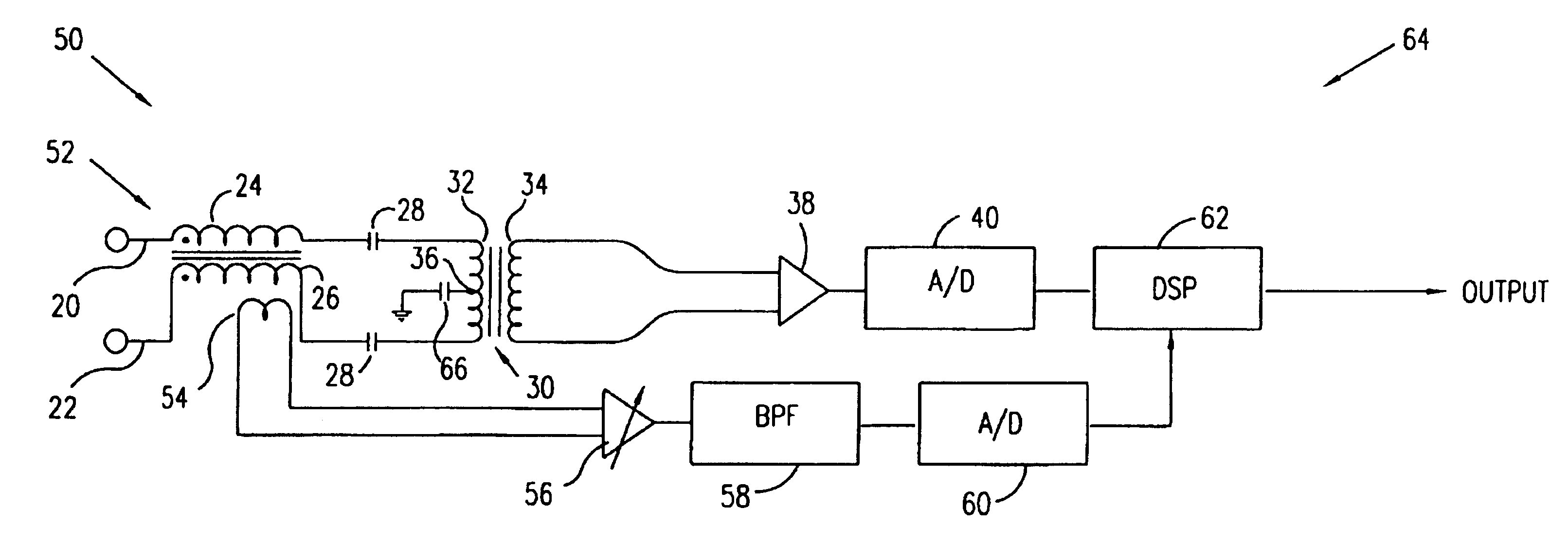
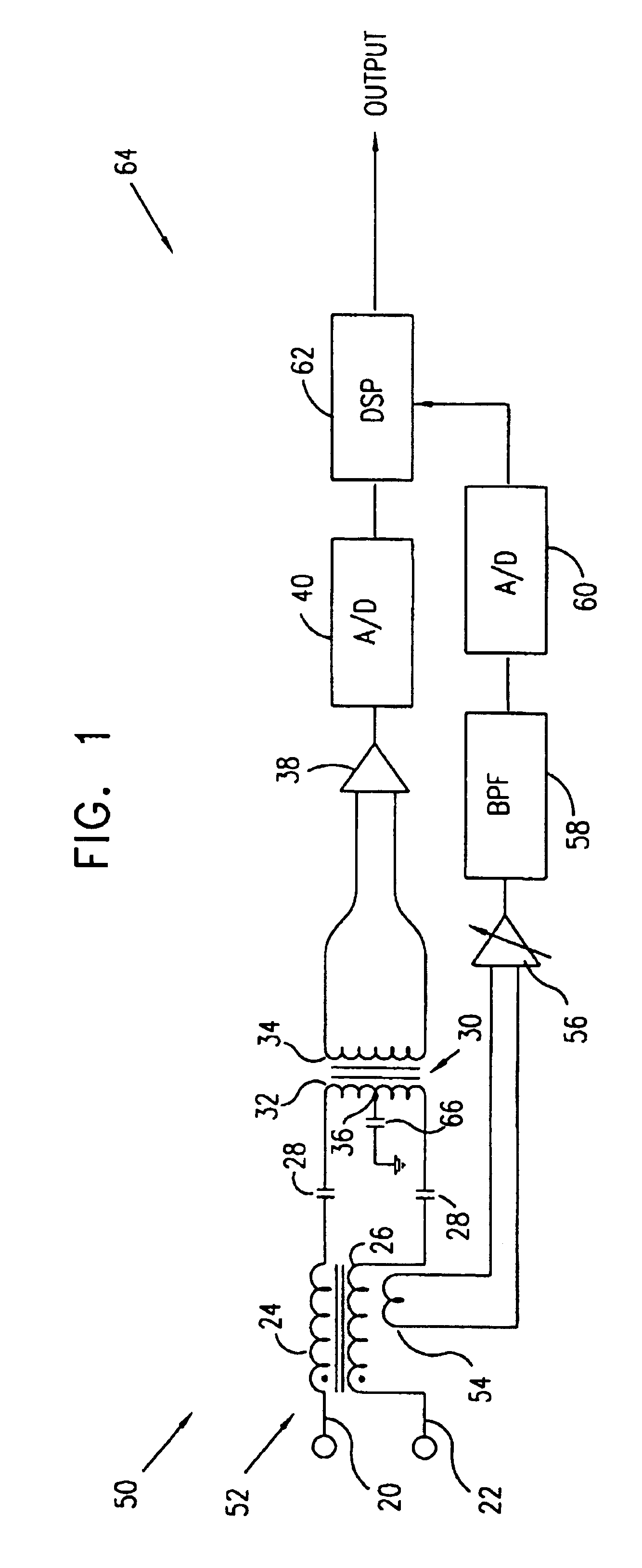
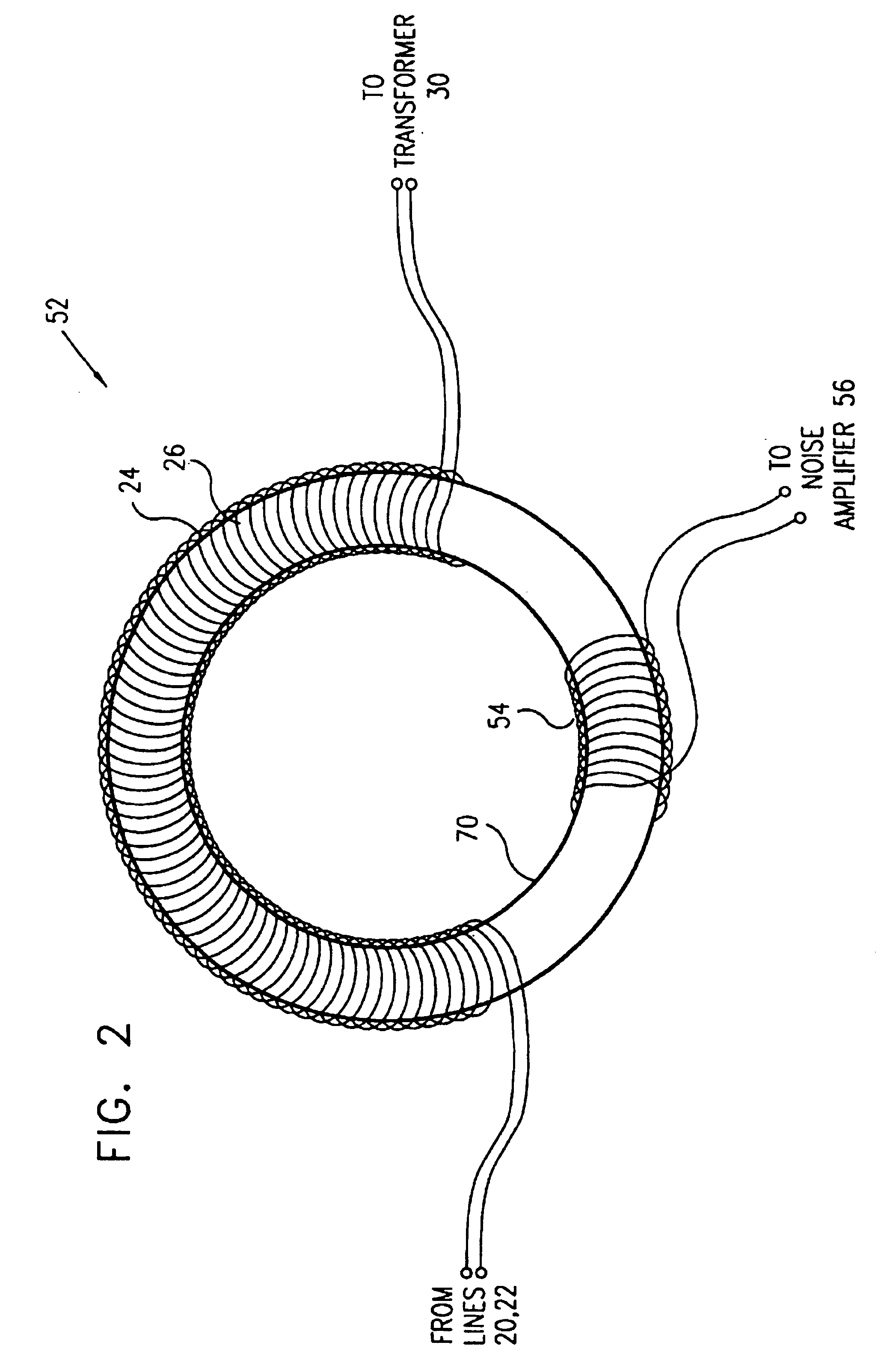
[0030]FIG. 1 is a schematic circuit diagram showing a receiver 50 for high-speed data signals, in accordance with a preferred embodiment of the present invention. Signals are input to the receiver from input lines 20 and 22 through a common-mode choke 52. Typically, the input lines are twisted pair telephone wires, and the receiver is part of a VDSL modem. Alternatively, receiver 50 may be coupled to input lines of other types and may be adapted to receive and process signals transmitted in accordance with other standards, as are known in the art. Choke 52 comprises parallel signal windings 24 and 26. The output of choke 52 is coupled via capacitors 28, serving as a high pass filter, to a primary winding 32 of a transformer 30. A secondary winding 34 of the transformer is coupled to processing circuitry 64, which processes the signals as described further hereinbelow. Preferably, primary winding 32 has a center tap 36, which is grounded through a capacitor 66, in order to ensure tha...


PUM


Abstract

A receiver for high-speed data communications, which receives a differential signal through a pair of signal lines. The receiver includes a common-mode choke, which has first and second signal windings, which are respectively coupled in series to the pair of signal lines so as to attenuate common-mode interference in the differential signal. The choke also has a sampling winding, which is inductively coupled to the signal windings so as to generate a sampled signal responsive to current flowing in the signal windings. Signal processing circuitry is coupled to receive the sampled signal from the sampling winding and to receive the differential signal from the signal windings and to process the differential signal responsive to the sampled signal.

Description

FIELD THE INVENTION[0001]The present invention relates generally to high-speed data communications over telephone cables, and specifically to methods and systems for rejection of radio frequency (RF) noise in Digital Subscriber Line (DSL) modems.BACKGROUND OF THE INVENTION[0002]Digital Subscriber Line (DSL) is a modem technology that enables broadband digital data to be transmitted over twisted-pair wire. This is the type of infrastructure that links most home and small business subscribers to their telephone service providers. DSL modems enable users to access digital networks at speeds tens to hundreds of times faster than current analog modems and basic ISDN service. DSL thus opens the most critical bottleneck in local-loop access to high-speed networks, such as Asynchronous Transfer Mode (ATM) and Internet Protocol (IP) networks, without requiring major investments in new infrastructure. DSL systems use special line signals that are well-adapted to the characteristics of twisted...

Claims


Application Information

Patent Timeline
IPC IPC(8): H04B3/50H04B3/30H04L25/02H04L25/10H04L27/00
CPCH04B3/30H04L25/0274H04L25/0292H04L25/10H04L27/0002
Inventor VITENBERG, ROMAN
Owner STMICROELECTRONICS SRL
Why Eureka
Try Eureka