Ink delivery and printing method for phasing printing systems

a printing system and phasing technology, applied in the field of printing systems, can solve the problems of failure of the printing system, and failure of the system,

Inactive Publication Date: 2005-06-30
XEROX CORP
View PDF2 Cites 28 Cited by
  • Summary
  • Abstract
  • Description
  • Claims
  • Application Information

AI Technical Summary

Problems solved by technology

One object of the control strategy is to avoid the printing system running out of ink while trying to print, because such an event can be a catastrophic failure to the system.
In the situation where an ink stick jam has occurred, i.e., the solid ink stick is obstructed from sliding down the ink loader tray to engagement with the heater, the continued supply of energy to the heater would not be able to melt the solid ink stick, because the stick was spaced from the heater itself.
If the reservoir were to actually run dry, the printing system would suffer a catastrophic failure and would be unable to print.
In addition, the continued application of the power to the elements of the heater could cause high temperature damage to the heater itself and to adjacent componentary.
The print head could become clogged requiring an expensive maintenance repair with significant printer down time.
If the measuring device did not indicate a refill of the reservoir during the time out period, the controller would disable the application of energy to the heater, thus assuming an ink stick jam.
Since the time out is based on the maximum possible ink usage, the printer was frequently not allowed to print which caused the printing rate to fall below specifications.
In a maximum fill printing operation, the smaller reservoirs can be drained relatively quickly so that a time-out operation before assessing an ink stick jam presents an unacceptable risk of a reservoir going dry and consequential damage to the print head and the jets therein.

Method used


Image

  • Ink delivery and printing method for phasing printing systems
  • Ink delivery and printing method for phasing printing systems
  • Ink delivery and printing method for phasing printing systems

Examples


Embodiment Construction

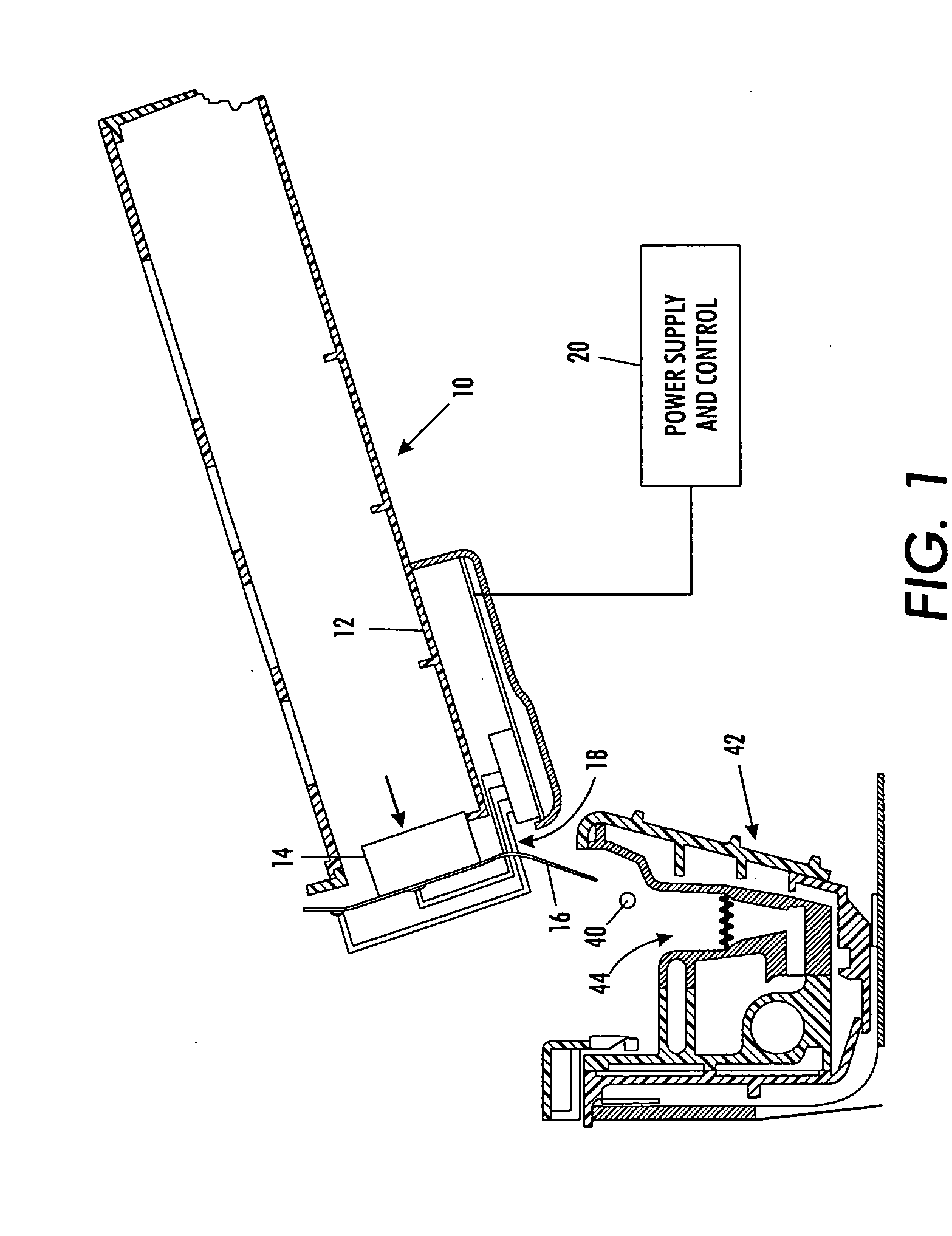
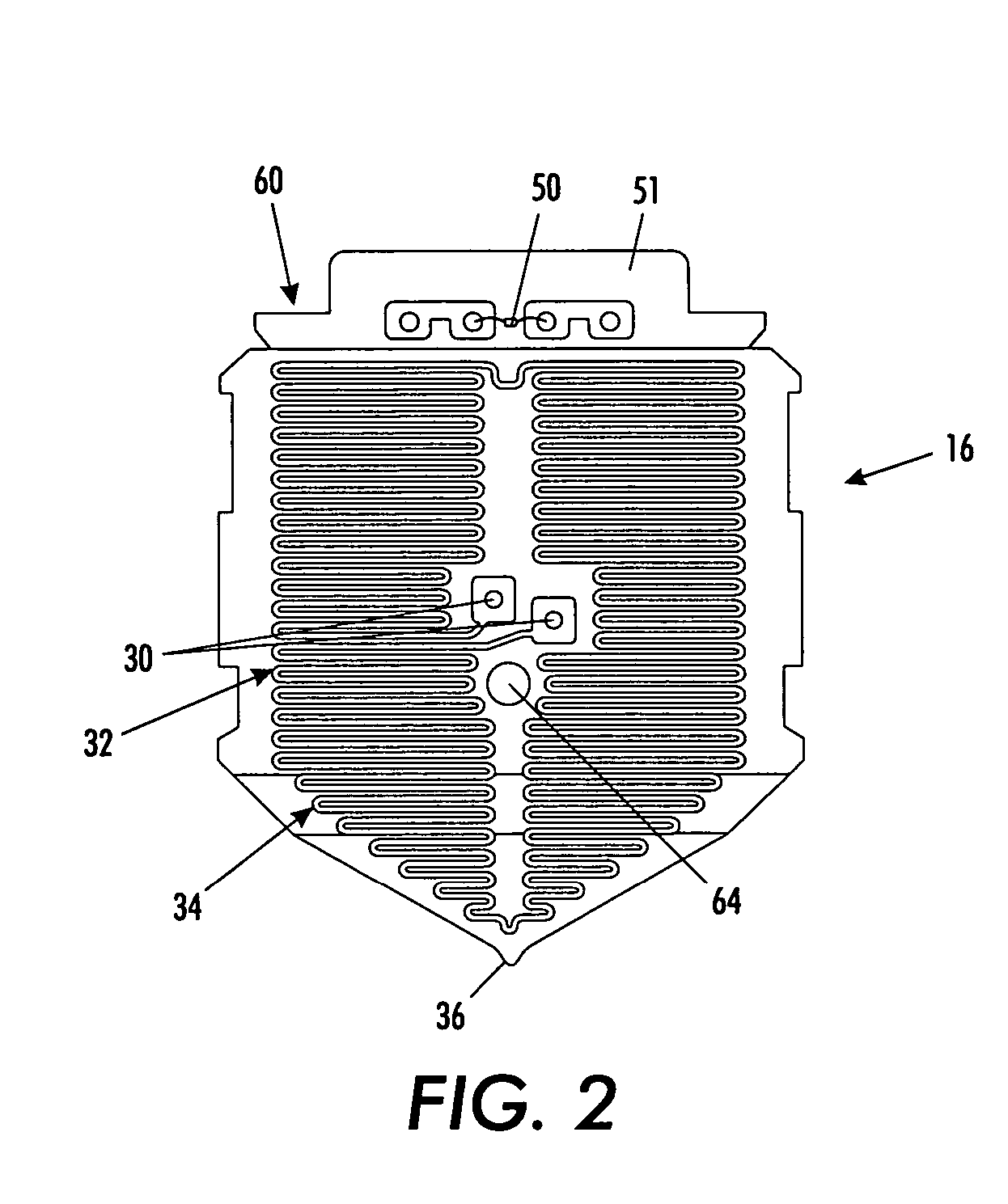
[0014] With reference to FIG. 1, the basic elements of an ink supply system in an ink “phase-changing” printing system can be seen. Ink loader assembly 10 includes a tray 12 for holding a solid phase ink stick 14. An ink melt heater 16 is disposed at an open end 18 of the tray to contact a proximate portion of the ink stick and to allow for egress of liquid phase ink during heating from the tray 10. The heating plate 16 receives its heating energy from a power supply and control system 20. The heating element includes an assembly with resistance traces thereon so that electrical energy supplied thereto can be converted to heat energy.

[0015]FIG. 1 is intended to illustrate an accurate positional disposition of the ink stick in the tray 11 to illustrate that the ink stick is urged against the heater plate 16 by both gravity and some other applied force means such as a spring bias (not shown) or the like. If, as the ink stick 14 is urged towards the heating plate 16, some obstruction ...


PUM


Abstract

A method and system is provided for more accurately determining ink in-flow and out-flow to a reservoir in a solid-to-liquid ink phasing delivery system for supplying ink to a printer. The printer throughput is safely maximized with a software algorithm that measures the ink available in the printer reservoir for printing. The algorithm is based on the known amount of ink in the reservoir when a level sensor probe is tripped and then calculates additional changes in ink volume. The process is done until the algorithm determines the reservoir volume is below a predetermined minimum level when the level sense probe senses ink. The algorithm calculates the ink leaving the reservoir using an out-flow model based on pixel counting and calculates ink entering the reservoir using an in-flow model based on a minimum guaranteed amount of ink delivered from the melt heater. A time out period is further calculated in which the reservoir should be refilled, and if not, the system is checked for an ink stick jam.

Description

BACKGROUND [0001] The present exemplary embodiments relate to printing systems and, in particular, printing devices which utilize a supply of colored inks to be communicated to a print head for document printing. More particularly, the present embodiments utilize solid ink sticks as the supply ink, which must be heated to a liquid form before being capable of communication to the print head. Such systems are commercially available under the PHASER® mark from Xerox Corporation. [0002] The present embodiments concern the structure, control system and operation methods of the heater element for causing a phase change in the solid ink supply to a liquid form capable of fluid communication to a print head for document printing. [0003] The basic operation of such phasing print systems comprises the melting of a solid ink stick, its communication to a reservoir for interim storage, and then a supply process from the reservoir to a print head for printing of a document. One object of the co...

Claims


Application Information

Patent Timeline
Patent Type & Authority Applications(United States)
IPC IPC(8): B41J2/175B41J2/195
CPCB41J2/17593B41J2/17566
Inventor GODIL, AMIN M.HINDMAN, LARRY E.THORNTON, AMY B.
Owner XEROX CORP
Why Eureka
Try Eureka