Inkjet head and inkjet printer

Active Publication Date: 2005-06-30
BROTHER KOGYO KK
View PDF5 Cites 4 Cited by
  • Summary
  • Abstract
  • Description
  • Claims
  • Application Information

AI Technical Summary

Benefits of technology

[0008] In view of the foregoing, it is an object of the present invention to provide an inkjet head that suppress structural cross-talk occurring when the volume of pressure chamber

Problems solved by technology

As the density of pressure chambers continues to increase in this type of inkjet head in recent years in order to meet high resolution and high-speed printing needs, a problem called structural cross-talk has arisen.
The structural cross-talk means that deformation in the piezoelectric sheet

Method used


Image

  • Inkjet head and inkjet printer
  • Inkjet head and inkjet printer
  • Inkjet head and inkjet printer

Examples


Example

[0027] An inkjet head according to a first embodiment of the present invention will be described next. It should be noted that the direction expressions such as “front”, “rear”, “above”, “below”, “top”, and “bottom” are used throughout the description to define the various parts when a printer is disposed in an orientation in which it is intended to be used. The inkjet head according to a first embodiment of the present invention is provided in an inkjet printer (not shown) for ejecting ink onto a paper conveyed in the inkjet printer in order to record images on the paper.

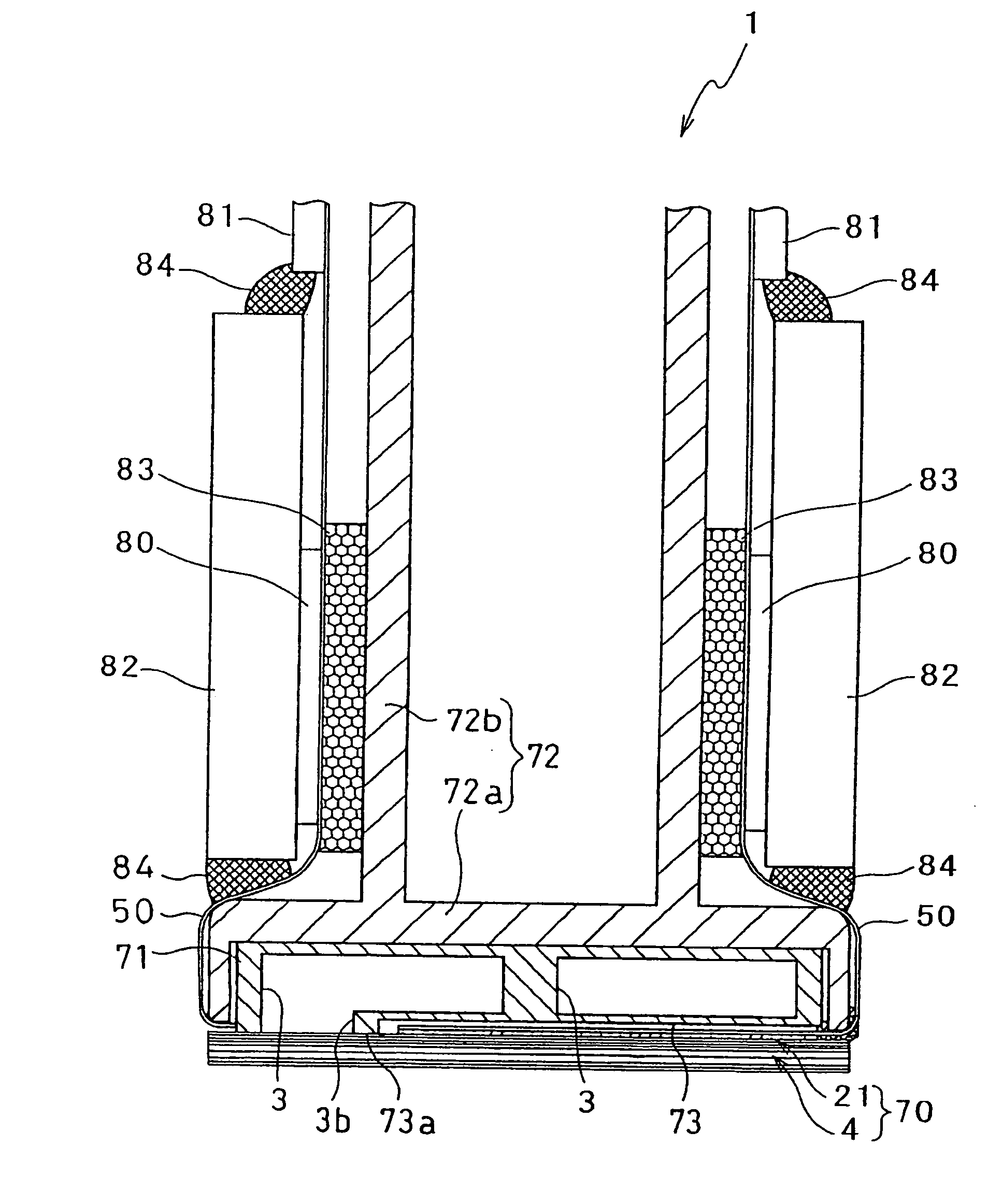
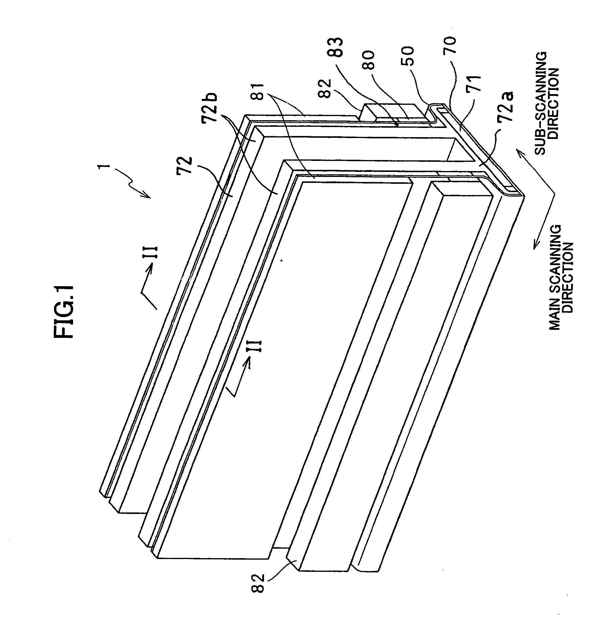
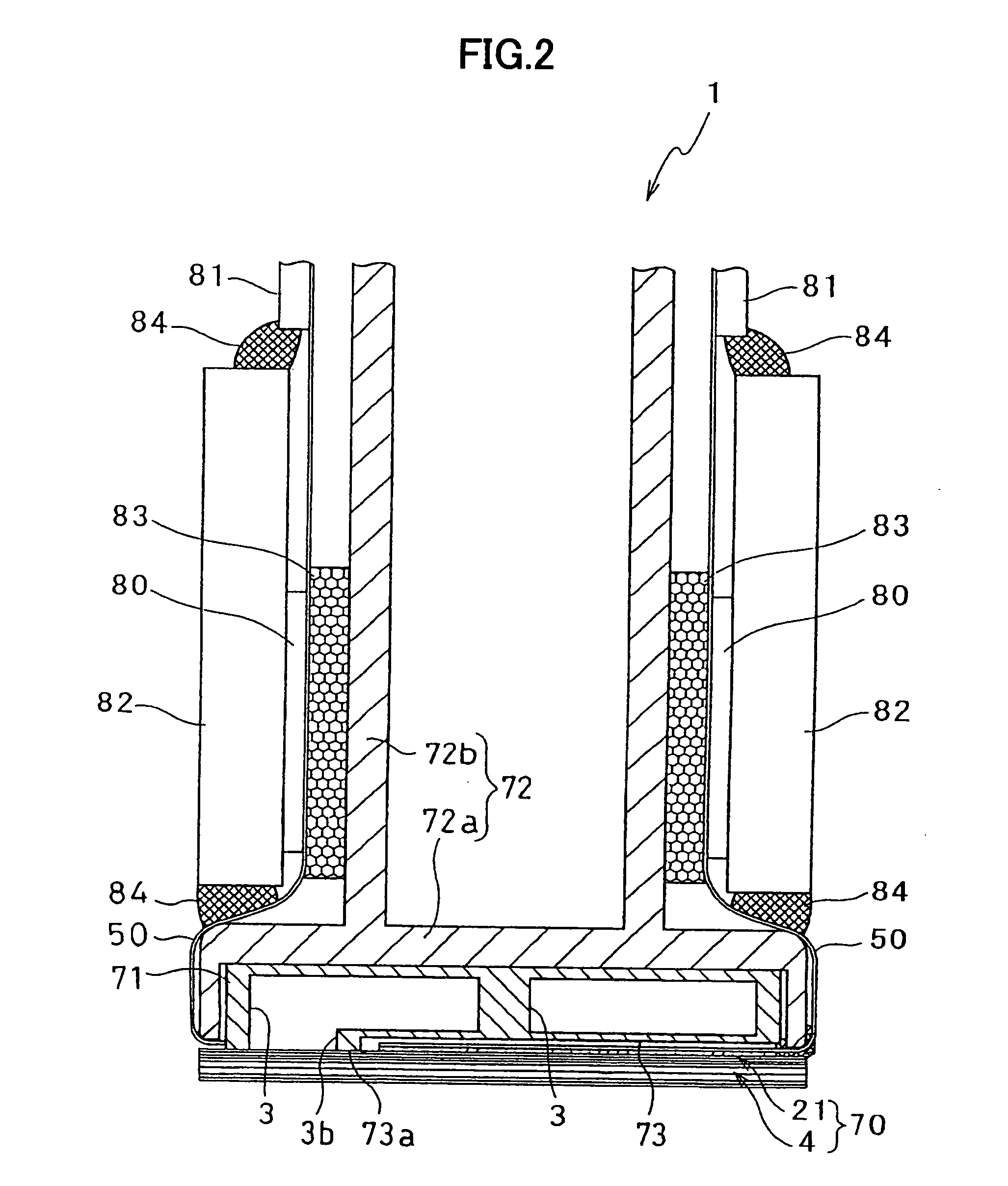
[0028]FIGS. 1 and 2 show the inkjet head 1 having a main head member 70 for ejecting ink to paper and a base block 71. The main head member 70 has a flat rectangular shape extending in a main scanning direction. The base block 71 has two ink reservoirs 3 for supplying ink to the main head member 70. The two ink reservoirs 3 are positioned above the main head member 70.

[0029] The main head member 70 includes: a ch...

Example

[0080] Next, an inkjet printer according to a second embodiment of the present invention will be described. FIG. 15 shows the inkjet printer 101 of the second embodiment. The inkjet printer 101 is a color inkjet printer having four inkjet heads 1A. Each of the inkjet heads 1A has the same structure as that of the inkjet head 1 of the first embodiment except the position of the coil 61. The inkjet printer 101 has a paper supply unit 111 and a discharge unit 112.

[0081] The inkjet printer 101 has a paper conveying path formed inside for conveying paper from the paper supply unit 111 to the discharge unit 112. A pair of conveying rollers 105a and 105b for pinching and conveying paper loaded in the paper supply unit 111 is disposed on the downstream side of the paper supply unit 111. Paper is conveyed from the left side of the drawing toward the right by the conveying rollers 105a and 105b. Two belt rollers 106 and 107 and an endless conveying belt 108 looped around the belt rollers 106...


PUM


Abstract

An inkjet head in which cross-talk between adjacent pressure chambers is suppressed. The inkjet head has a channel unit having pressure chambers and nozzles communication with the pressure chambers, and an actuator unit fixed to one surface of the channel unit for changing the volume of the pressure chamber. The actuator unit includes individual electrodes provided opposed to the plurality of pressure chambers for receiving a drive signal to change the volume of the pressure chamber; a common electrode provided over the plurality of pressure chambers; a piezoelectric sheet provided between the individual electrode and the common electrode; and an independent electrode provided between adjacent individual electrodes and electrically isolated from the common electrode and the individual electrodes. An inductor is electrically connected between the independent electrode and a portion whose electric potential is substantially the same as that of the common electrode.

Description

BACKGROUND OF THE INVENTION [0001] 1. Field of the Invention [0002] The present invention relates to an inkjet head for ejecting ink onto a recording medium and an inkjet printer for performing printing operations with the inkjet head. [0003] 2. Description of the Related Art [0004] An inkjet head distributes ink supplied from an ink tank to a plurality of pressure chambers to eject ink through nozzles that are in fluid communication with the pressure chambers by selectively applying pressure in pulses to the pressure chambers one of methods for selectively applying pressure to the pressure chambers is to use an actuator unit formed of a plurality of ceramic piezoelectric sheets laminated together. [0005] One inkjet head having this type of actuator unit is disclosed in Japanese unexamined patent application publication HEI-4-341852 (FIG. 1). The inkjet head has a plurality of individual electrodes disposed opposite a plurality of pressure chambers for changing the volume of the pre...

Claims


Application Information

Patent Timeline
IPC IPC(8): B41J2/055B41J2/045B41J2/14
CPCB41J2/14209B41J2002/14217B41J2002/14225B41J2202/20B41J2002/14459B41J2002/14491B41J2002/14306
Inventor IWAO, NAOTO
Owner BROTHER KOGYO KK
Why Eureka
Try Eureka