Image reading apparatus and drive control method therefor

a technology of image reading and drive control, which is applied in the direction of acquiring/reconfiguring fingerprints/palmprints, mechanical pattern conversion, instruments, etc., can solve the problems of damage to the sensor, cost, time and labor, and achieve the effect of improving the use convenience and improving the reliability of the image reading apparatus

Inactive Publication Date: 2005-06-30
CASIO COMPUTER CO LTD
View PDF6 Cites 70 Cited by
  • Summary
  • Abstract
  • Description
  • Claims
  • Application Information

AI Technical Summary

Benefits of technology

[0011] The present invention relates to an image reading apparatus for reading an image of a medium placed on a detection surface formed by arranging a plurality of sensors, and has an advantage that reliability of the image reading apparatus can be improved and usage convenience of the image reading apparatus can be improved by overcoming problems:

Problems solved by technology

However, this image reading apparatus has the following problems.
This might damage the sensors 10p and the drive circuit 50p, or cause malfunctioning.
Therefore, even in a case where the medium loses contact with the sensors 10p due to some cause in the middle of the image reading operation,

Method used


Image

  • Image reading apparatus and drive control method therefor
  • Image reading apparatus and drive control method therefor
  • Image reading apparatus and drive control method therefor

Examples


first embodiment

of Image Reading Apparatus

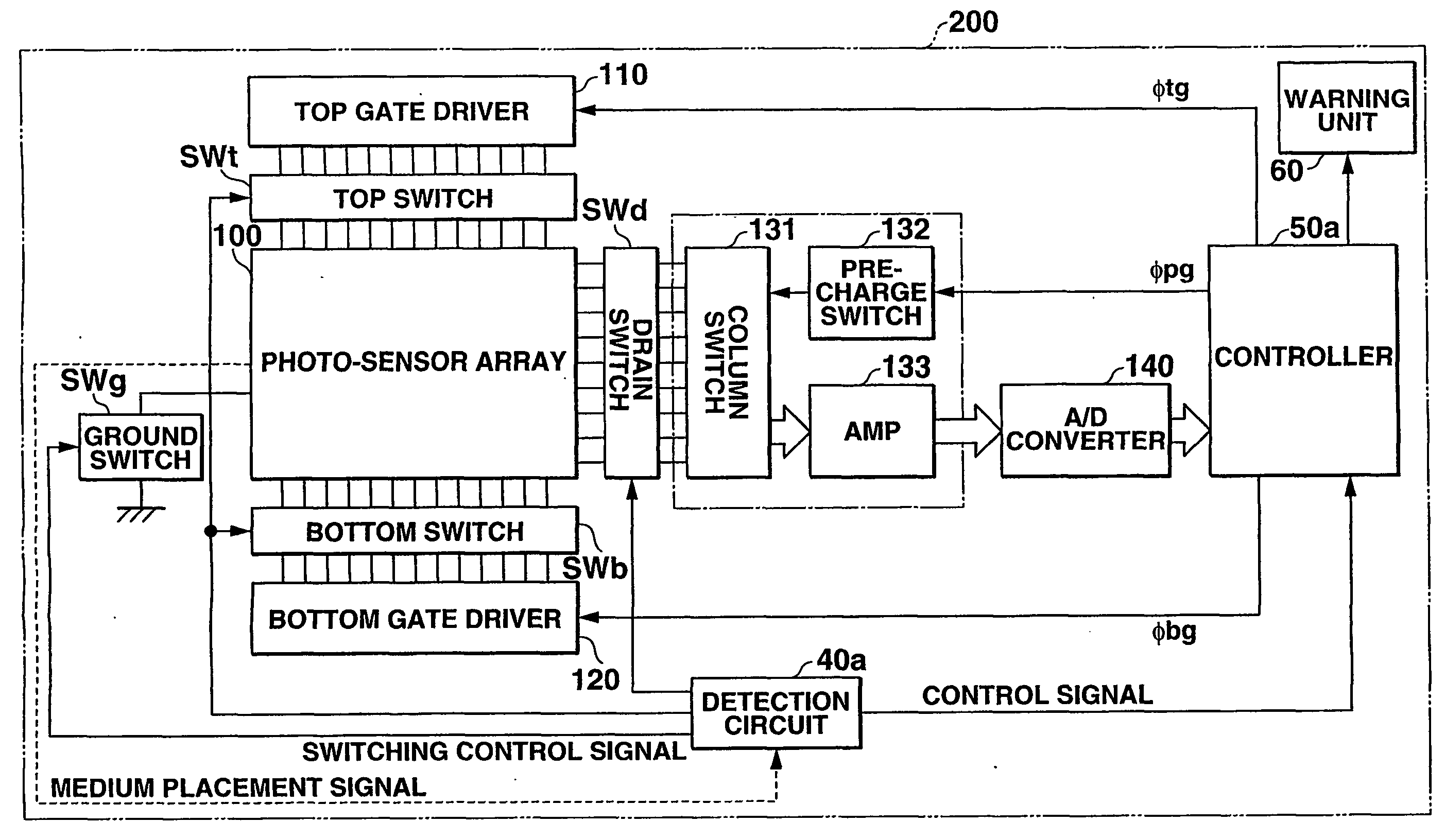
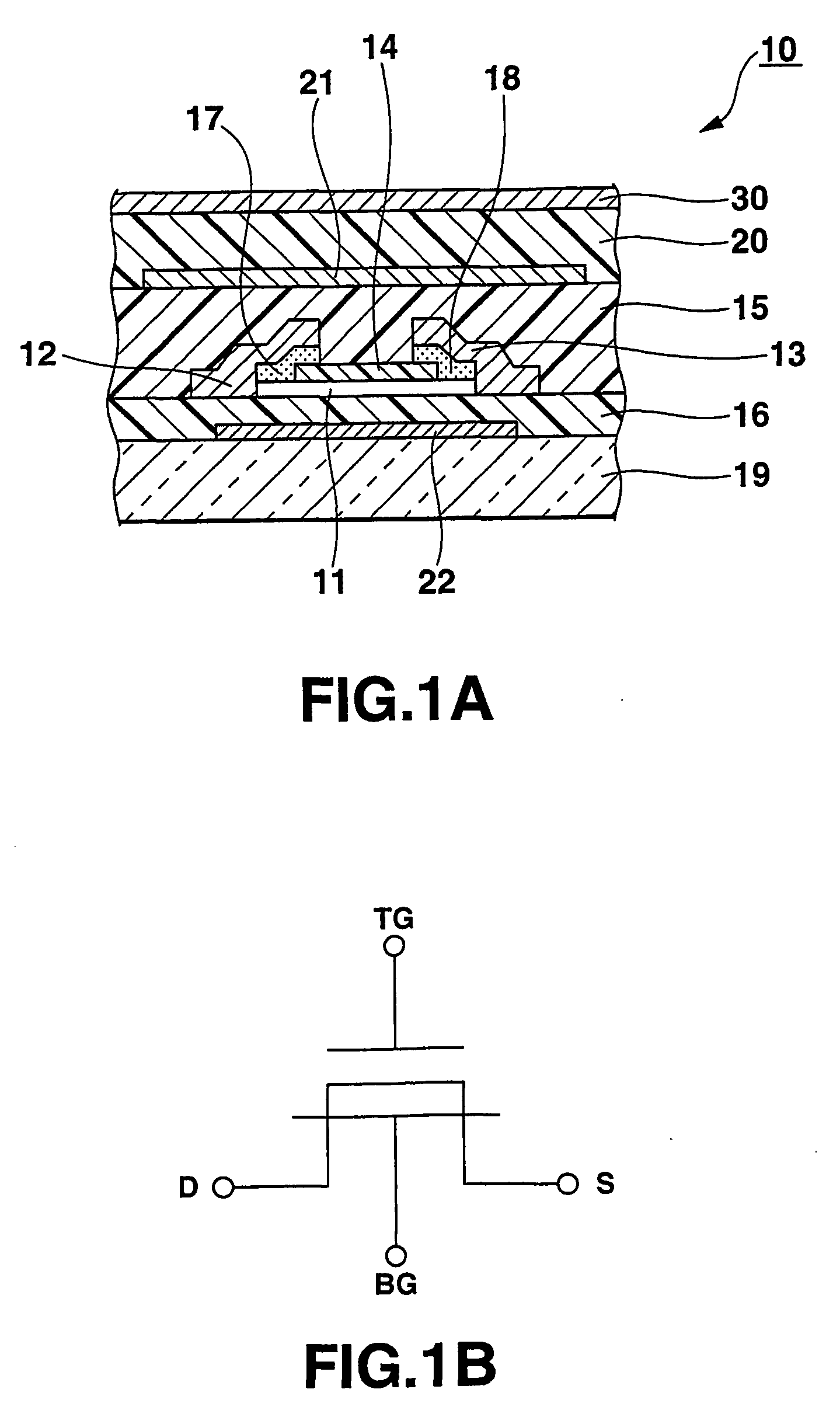
[0085]FIG. 11 is a block diagram showing the whole structure of the image reading apparatus according to a first embodiment of the present invention. FIG. 12 is a diagram showing a structure of the principal part of the image reading apparatus according to the present invention. FIG. 13 is a diagram showing a circuit structure of the principal part of the image reading apparatus according to the present embodiment.

[0086] The following explanation will be made by timely referring to the structure of the above described photo-sensor system (see FIG. 5 and FIG. 6). Components same as components shown in FIG. 1A, FIG. 1B, and FIG. 5 will be denoted by the same reference numerals, and explanation of such components will be simplified or omitted.

[0087] As shown in FIG. 11, the image reading apparatus 200 according to the present invention 200 comprises a photo-sensor system including a photo-sensor array 100, a top gate driver 110, a bottom gate driver 120, a d...

second embodiment

of Image Reading Apparatus

[0117]FIG. 16 is a diagram showing a principal part of an image reading apparatus according to a second embodiment of the present invention.

[0118] The explanation will be made below by timely referring to the structure of the above described photo-sensor system (see FIG. 5 and FIG. 6). Components same as components shown in FIG. 1A, FIG. 1B, and FIG. 5 will be denoted by the same reference numerals, and explanation of such components will be simplified or omitted.

[0119] The present embodiment relates to a structure for driving the photo-sensor array in accordance with whether a medium is placed on the detection circuit, in the image reading apparatus having the same structure as the above described first embodiment.

[0120] As shown in FIG. 16, the image reading apparatus according to the present embodiment comprises a detection circuit (medium detector) 40b and a controller (operation controlling means) 50b. The detection circuit 40b detects whether a med...


PUM


Abstract

There is provided an image reading apparatus which reads an image pattern of a medium placed on a detection surface of a sensor array (100). In a waiting state, electrical connection between the sensor array (100) and a drive controller (110, 120) is cut off, and whether a medium is placed on the detection surface or not is detected. When a medium is placed on the detection surface, the sensor array (100) and the drive controller (110, 120) are electrically connected and an image reading operation is started. In a case where the medium is separated from the detection surface during the image reading operation, the image reading operation is suspended and the image reading apparatus is set to the waiting state.

Description

TECHNICAL FIELD [0001] The present invention relates to an image reading apparatus. Particularly, the present invention relates to an image reading apparatus which has a sensor array formed of a plurality of sensors on which a medium having an image pattern is placed so that it contacts the array, and reads the image pattern of the medium by driving the sensor array to perform scanning. BACKGROUND ART [0002] Conventionally, as a technique for reading two-dimensional image patterns such as printings, photographs, or fingerprints or other patterns having slight height, there has been known an image reading apparatus which has a sensor array formed of opto-electric conversion elements arranged in matrix or in line, and by driving the sensor array to perform scanning, reads an image pattern of a medium which is placed in contact with a detection surface provided on the sensor array. [0003] Such an image reading apparatus is now being greatly researched and developed in order to apply th...

Claims


Application Information

Patent Timeline
IPC IPC(8): G06K9/00
CPCG06K9/0002G06V40/1306G06F18/00
Inventor MIZUTANI, YASUSHI
Owner CASIO COMPUTER CO LTD
Why Eureka
Try Eureka