Image combiner and image display unit

Inactive Publication Date: 2005-06-30
NIKON CORP
View PDF7 Cites 76 Cited by
  • Summary
  • Abstract
  • Description
  • Claims
  • Application Information

AI Technical Summary

Benefits of technology

[0045] As was described above, the present invention can provide an image display device which is capable of achieving an improvement in the image quality of the display image in cases where the center of the pupil of the eye of the user deviates from

Problems solved by technology

However, this is an argument that is limited solely by the value of the diffraction efficiency in the case of illumination by light of a single wavelength; research has not p

Method used


Image

  • Image combiner and image display unit
  • Image combiner and image display unit
  • Image combiner and image display unit

Examples


Example

[0073] Image combiners and image display devices constituting working configurations of the present invention will be described below with reference to the figures.

[First Working Configuration]

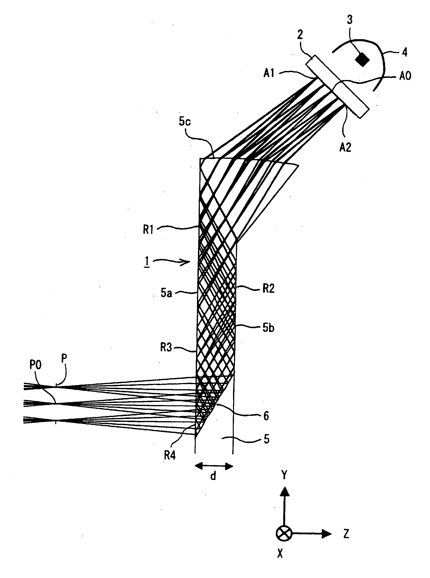
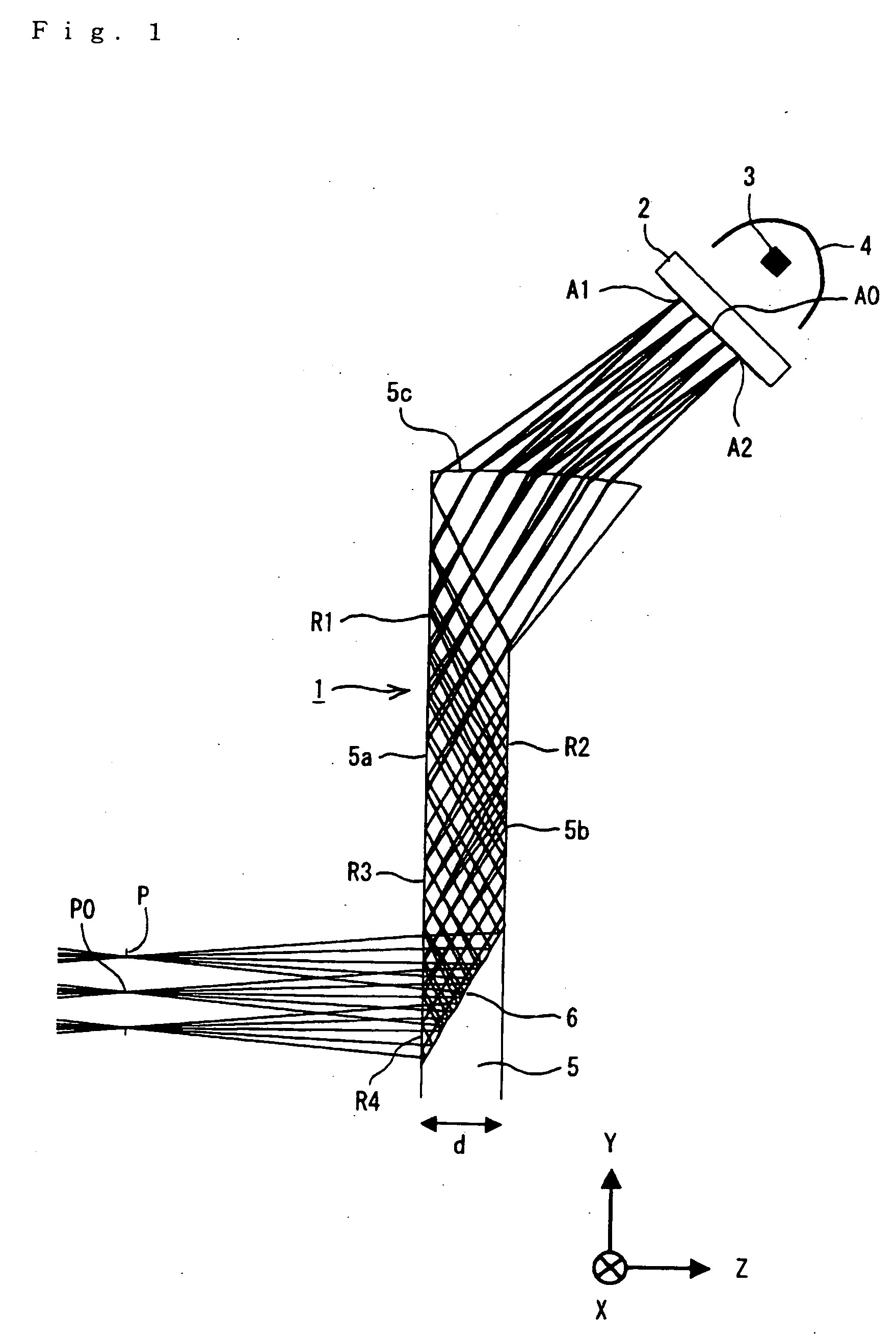
[0074]FIG. 1 is a diagram which shows the construction of an image display device constituting a first working configuration of the present invention, and (in schematic terms) the path of the light rays (only the light rays from the image display element 2) in this image display device.

[0075] Here, an X axis, a Y axis and a Z axis that are mutually perpendicular are defined as shown in FIG. 1. Specifically, the left-right direction in the plane of the page in FIG. 1 is taken as the Z axis, and the direction in which the Z coordinate value increases is defined as “right.” The vertical direction in the plane of the page in FIG. 1 is taken as the Y axis, and the direction in which the Y coordinate value increases is defined as “up.” The direction perpendicular to the plane of the page in FIG. ...


PUM


Abstract

During use, a plate-form part 5 which is constructed from an optical material and which corresponds to a spectacle lens is positioned in front of the eye of the user which is disposed in the vicinity of the exit pupil P of an image combiner 1. The combiner 1 causes light from an image display element 2 to be superimposed on light that is transmitted through the plate-form part 5 so as to pass through the thickness of the plate-form part 5 from the front of the plate-form part 5, and conducts this light to the eye. The light from the image display element 2 reaches the eye of the user after being diffracted and reflected by a reflective type HOE 6 inside the plate-form part 5. The wavelength at which the diffraction efficiency shows a maximum value when the chief rays that are emitted from the center of the display part of the image display element 2 are diffracted and reflected by the reflective type HOE 6 and the wavelength at which the diffraction efficiency shows a maximum value when the chief rays that are emitted from the peripheral portions of the display part in a specified direction are diffracted and reflected by the reflective type HOE 6 are substantially different. As a result, it is possible to improve the image quality of the display images that are obtained in cases where the center of the pupil of the eye of the user deviates from the center of the exit pupil of the image combiner.

Description

[0001] This is a continuation of PCT International Application No. PCT / JP2003 / 009430 filed on Jul. 25, 2003, which is hereby incorporated by reference.TECHNICAL FIELD [0002] The present invention relates to an image combiner which makes it possible for the user to view an image based on light from the front such as the outside world and a display image that is superimposed on this first image, and an image display device such as a head-mounted display using this image combiner. BACKGROUND ART [0003] In the past, for example, the image display devices disclosed in Japanese Patent Application Kokai No. 2000-352689 and Japanese Patent Application Kokai No. 2001-264682 have been known as so-called see-through type head-mounted image display devices (head-mounted displays) which allow the user to view a display image superimposed on a view of the outside world while observing the conditions of this outside world. Furthermore, Japanese Patent Application Kokai No. 2001-264682 discloses no...

Claims


Application Information

Patent Timeline
IPC IPC(8): G02B5/32G02B25/00G02B17/08G02B27/00G02B27/01G02B27/02G02B27/10H04N5/74
CPCG02B5/32G02B27/0081G02B27/0103G02B27/0172H04N5/7491G02B2027/0112G02B2027/0118G02B2027/0123G02B2027/0174G02B27/1086
Inventor OUCHI, YUMIKO
Owner NIKON CORP
Why Eureka
Try Eureka