Apparatus and method for controlling headlight in vehicle and headlight lamp having multifunction structure

US20050141232A1Inactive Publication Date: 2005-06-30CHON YOUNG ILL +1

Image

  • Apparatus and method for controlling headlight in vehicle and headlight lamp having multifunction structure
  • Apparatus and method for controlling headlight in vehicle and headlight lamp having multifunction structure
  • Apparatus and method for controlling headlight in vehicle and headlight lamp having multifunction structure

Examples


Embodiment Construction

[0046] The preferred embodiments of the present invention will be described with reference to the accompanying drawings. When giving the elements of each drawing a corresponding reference numeral, the same elements are given the same numeral references even through they are shown in different drawings. In addition, the known art functions and construction that are judged to make the gist of the present invention unclear will be omitted.

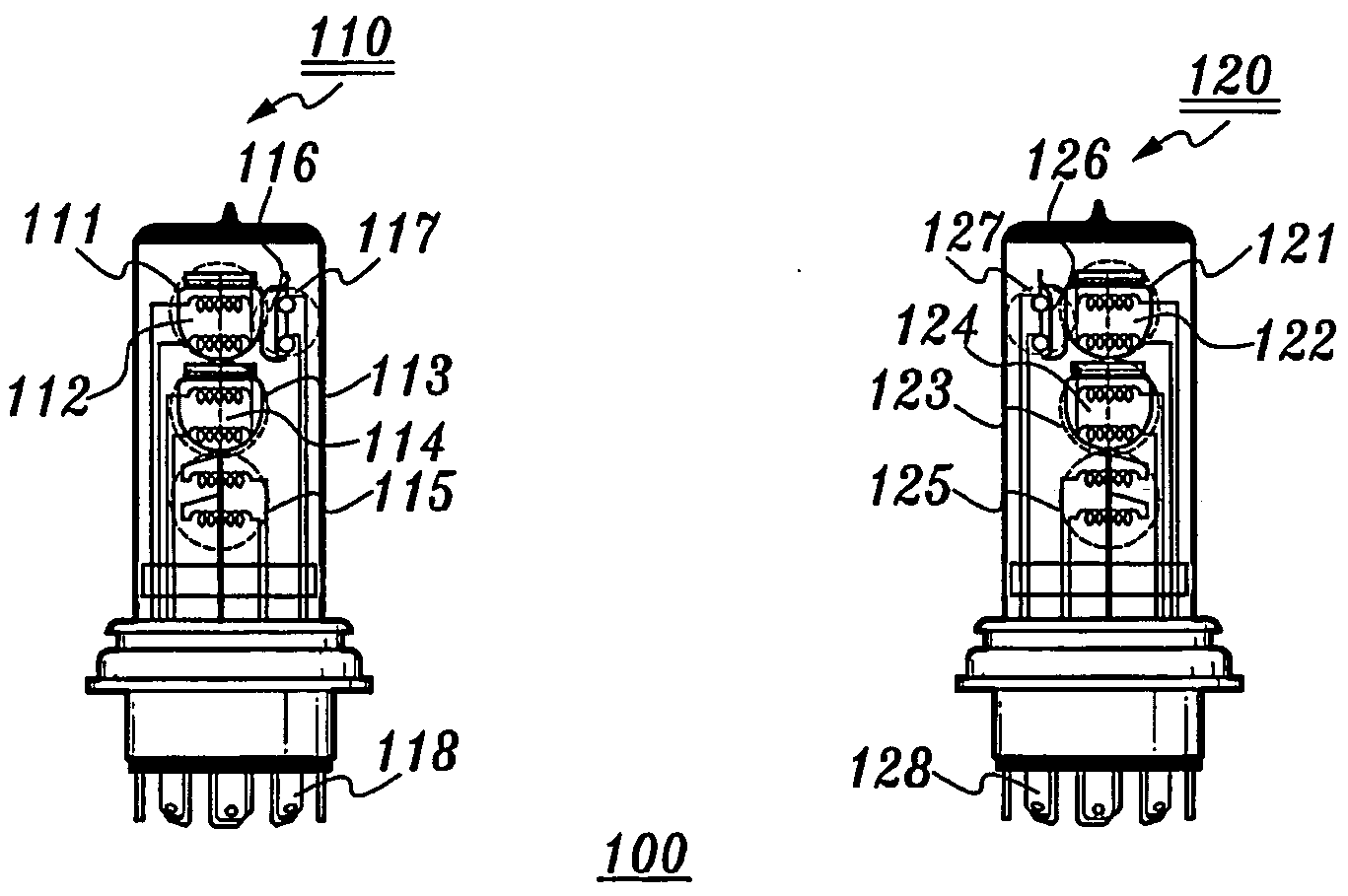
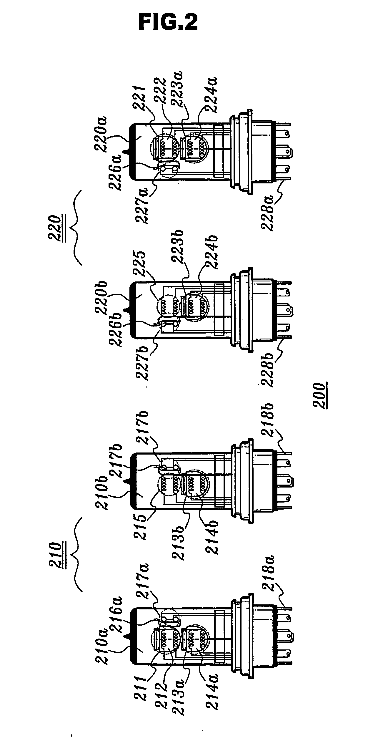
[0047]FIG. 1 is a view illustrating an integral type headlight lamp for a vehicle having a multifunction structure according to a preferred embodiment of the present invention, and FIG. 2 is a view illustrating a separation type headlight lamp for a vehicle having a multifunction structure according to a preferred embodiment of the present invention.

[0048] As shown in FIGS. 1 and 2, the multifunction structure adapted to a headlight of a vehicle according to the present invention is classified into an integration type 100 and a separation type 200. ...


PUM


Abstract

The present invention relates to a headlight lamp (110) having a multifunction structure in which a lighting angle of a headlight of a vehicle is automatically and manually controlled based on a running speed of a vehicle, a brightness of a headlight of an opponent vehicle and a surrounding brightness of a vehicle. The headlight lamp (110) includes a plurality of high angle headlight filaments (115), capable of lighting for providing a high angle beam to a vehicle, a plurality of low angle headlight filaments (111) capable of lighting for providing a low angle beam to the vehicle, low angle headlight reflection covers (112) provided in the low angle headlight filaments (111) respectively, for thereby allowing the light from the low angle headlight filaments (111) to have a low beam pattern angle, and external connection terminals.

Description

TECHNICAL FIELD [0001] The present invention relates to a headlight of a vehicle, and in particular to a headlight lamp having a multifunction structure in which a lighting angle of a headlight of a vehicle is automatically and manually controlled based on a running speed of a vehicle, a brightness of a headlight of an opponent vehicle and a surrounding brightness of a vehicle using a headlight lamp having a multifunction structure provided with a plurality of filaments for high, middle and low angle headlights. There is provided a disconnection prevention structure having a plurality of filaments for a disconnection of a filament of a headlight lamp. There is provided a headlight having a sufficient luminous intensity capable of implementing a sufficient sight distance for overcoming a problem that a driver's eyesight is bad due to a bad weather such as rain, etc. In addition, the present invention relates to an apparatus and method for controlling a headlight of a vehicle and a he...

Claims


Application Information

Patent Timeline
30 Jun 2005
Publication
US20050141232A1
IPC
B60Q1/14; B60Q1/04; F21V7/00; H01K9/08
CPC
B60Q1/1415; H01K9/08; F21S48/1317; F21S41/32; B60Q2900/40; B60Q1/04
Inventors
CHON, YOUNG-ILL; CHON, SANG-WOOK