
Optical disk device and phase difference detector

a technology of optical disk and detector, which is applied in the direction of instruments, recording signal processing, disposition/mounting of heads, etc., can solve the problem of long time processing and a relatively large circui

Inactive Publication Date: 2005-06-30
KK TOSHIBA
View PDF7 Cites 0 Cited by
  • Summary
  • Abstract
  • Description
  • Claims
  • Application Information

AI Technical Summary

Benefits of technology

[0011] According to another aspect of the present invention, there is provided a phase difference detector comprising: a comparison section configured to compare a first signal sampled at the first timing with a second signal sampled at the second timing; and detection sections configured to detect a phase difference signal of the first signal and the second signal by repeating comparison until the same value is attained by differing timing with respect to the first and the second timing when the same value is not attained in the first signal and the second signal in the comparison section.

Problems solved by technology

That is, since the circuit is an analog type detection circuit, there arises a problem in that a long time processing is required with a relatively large-scale circuit until a phase difference signal for the tracking control is obtained.

Method used


Image

  • Optical disk device and phase difference detector
  • Optical disk device and phase difference detector
  • Optical disk device and phase difference detector

Examples


Embodiment Construction

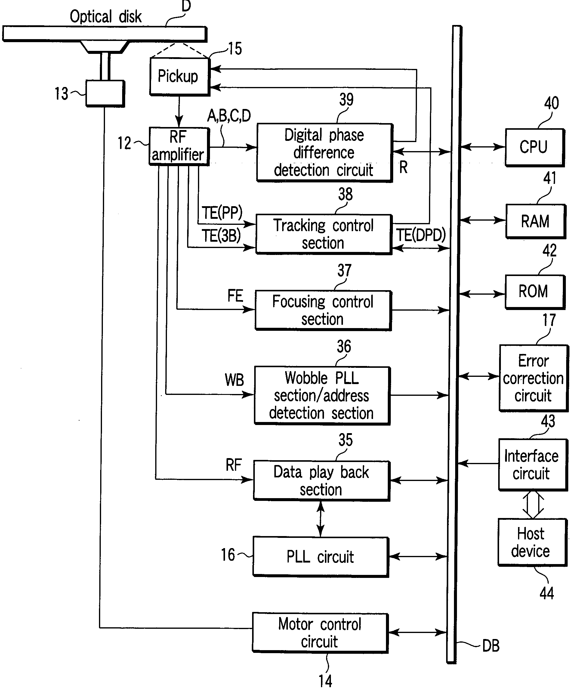
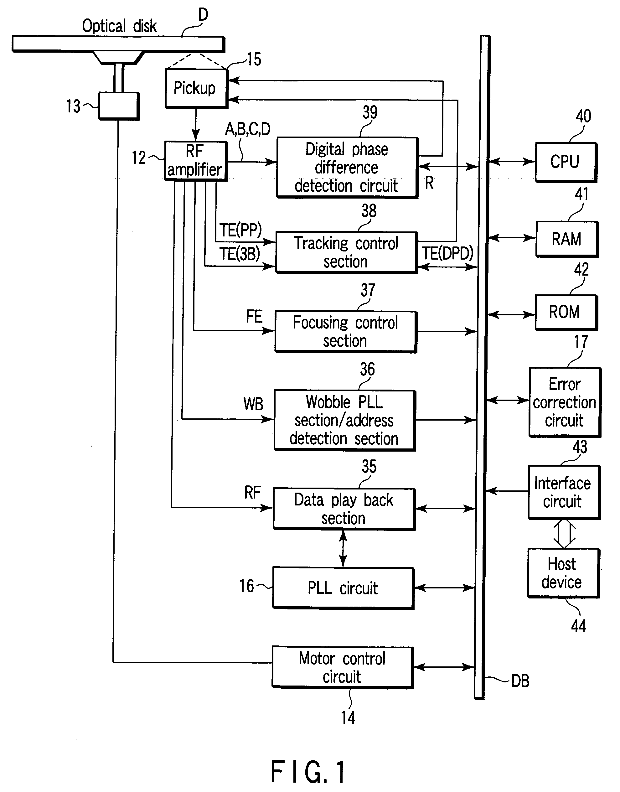
[0020] Hereinafter, one embodiment of the present invention will be explained in detail by referring to the drawings. The embodiment which will be described below will be explained by using as an example an optical disk device having a phase difference detection circuit for detecting a tracking error signal TE which is a phase difference of the tracking signal for use in the tracking control. However, the phase difference detector according to the present invention is a technology which can be applied when the phase difference of an analog signal is detected with a general electronic device.

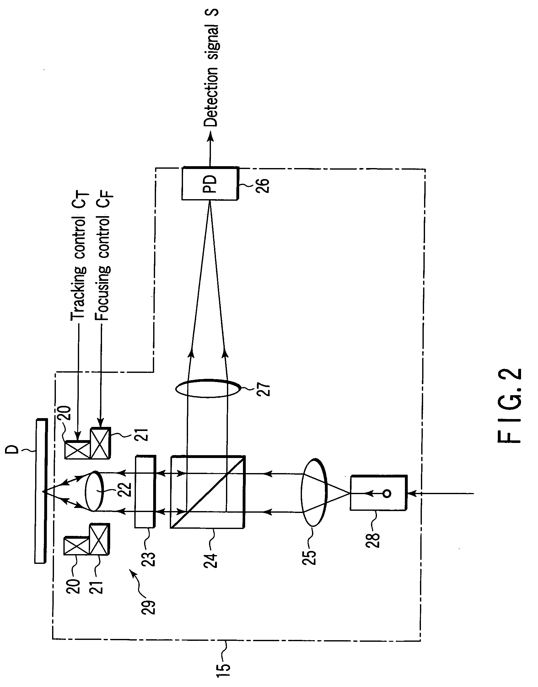
[0021]FIG. 1 is a block diagram showing an optical disk device for explaining the embodiment. FIG. 2 is a block diagram showing the detail of the pickup of the optical disk device according to the embodiment. FIG. 3 is a block diagram showing the detail of the digital phase difference detection circuit of the optical disk device according to the embodiment.

(Structure and Operation)

[0022] One ...


PUM

PropertyMeasurementUnit
phaseaaaaaaaaaa
phase differenceaaaaaaaaaa
frequencyaaaaaaaaaa

Abstract

A first reading signal to a fourth reading signal are acquired with a four division element from an optical disk. The first reading signal and a third reading signal are sampled and added at a predetermined timing to obtain a first addition signal, while the second reading signal and the fourth reading signal are sampled and added at a predetermined to obtain a second addition signal. A phase difference signal of the first addition signal and the second addition signal are detected by repeating comparison of the two signals until the same value is attained by differing sampling timing with respect to the first addition signal and the second addition signal when the same value is not attained in the first addition signal and the second addition signal in the comparison with the result that the tracking control is conducted based on the detected phase difference signal.

Description

CROSS-REFERENCE TO RELATED APPLICATIONS [0001] This application is based upon and claims the benefit of priority from prior Japanese Patent Application No. 2003-431163, filed Dec. 25, 2003, the entire contents of which are incorporated herein by reference. BACKGROUND OF THE INVENTION [0002] 1. Field of the Invention [0003] The present invention relates to an optical disk device and a phase difference detector and, more particularly to an optical disk device and a phase difference detector having a digital phase difference detection circuit that acquires a phase difference of a detection signal for a tracking control. [0004] 2. Description of the Related Art [0005] As is well known, an optical disk such as a DVD (Digital Versatile Disk) or the like is prevalent as a digital recording medium in recent years. Along with it, a high reliability is desired in the optical disk device for playing back such optical disk as well. In such optical disk, a memory area is provided on spiral track...

Claims


Application Information

Patent Timeline
Patent Type & Authority Applications(United States)
IPC IPC(8): G11B7/00G11B7/09
CPCG11B7/0906G11B7/09
Inventor KOJIMA, SATORUYONEZAWA, MINORU
Owner KK TOSHIBA
Learn More