Cooling device

a cooling device and cooling fluid technology, applied in the direction of electrical apparatus construction details, light and heating apparatus, laminated elements, etc., can solve the problems of inability to achieve sufficient heat dissipation, inability to manufacture distributing devices, and inability to symmetrically flow cooling fluid in all directions

Inactive Publication Date: 2005-06-30
DANFOSS SILICON POWER
View PDF8 Cites 32 Cited by
  • Summary
  • Abstract
  • Description
  • Claims
  • Application Information

AI Technical Summary

Benefits of technology

[0006] Because of the plurality of uniformly distributed outlet and drain openings a uniform heat dissipation and cooling of the entire cooling surface of the cooling plate is assured, essentially independently of the shape and number of the power components which may be wanted to be cooled. The same thing applies for a fluid to be cooled, such as gas or a liquid, which stands or comes into contact with the cooling surface of the cooling plate. Since the distributing device is comprised of several sandwiched plates, which bound the feed and drain channels, the manufacture of the distributing device is simple: the fashioning of the channels can take place on a outer side or both outer sides of a plate or of two plates, for example in a corresponding shaping tool. At the same time, as the case may be, in the same shaping tool the necessary outlet and drain openings can be formed in the first plate.
[0017] At least the first to the fifth plates can be made of plastic or metal and the cooling plate of metal. Also in the case of this platelike cooling device the plates accordingly can be made in simple ways.

Problems solved by technology

The manufacture of the distributing device is difficult, because the bores extending parallel to the plane of the cooling plate can be made only with great difficulty.
Therefore, the cooling fluid does not flow symmetrically in all directions from the jets to the central drain openings along and below the power components.
Consequently, at this place no sufficient heat dissipation is achievable.

Method used


Image

  • Cooling device
  • Cooling device
  • Cooling device

Examples


Embodiment Construction

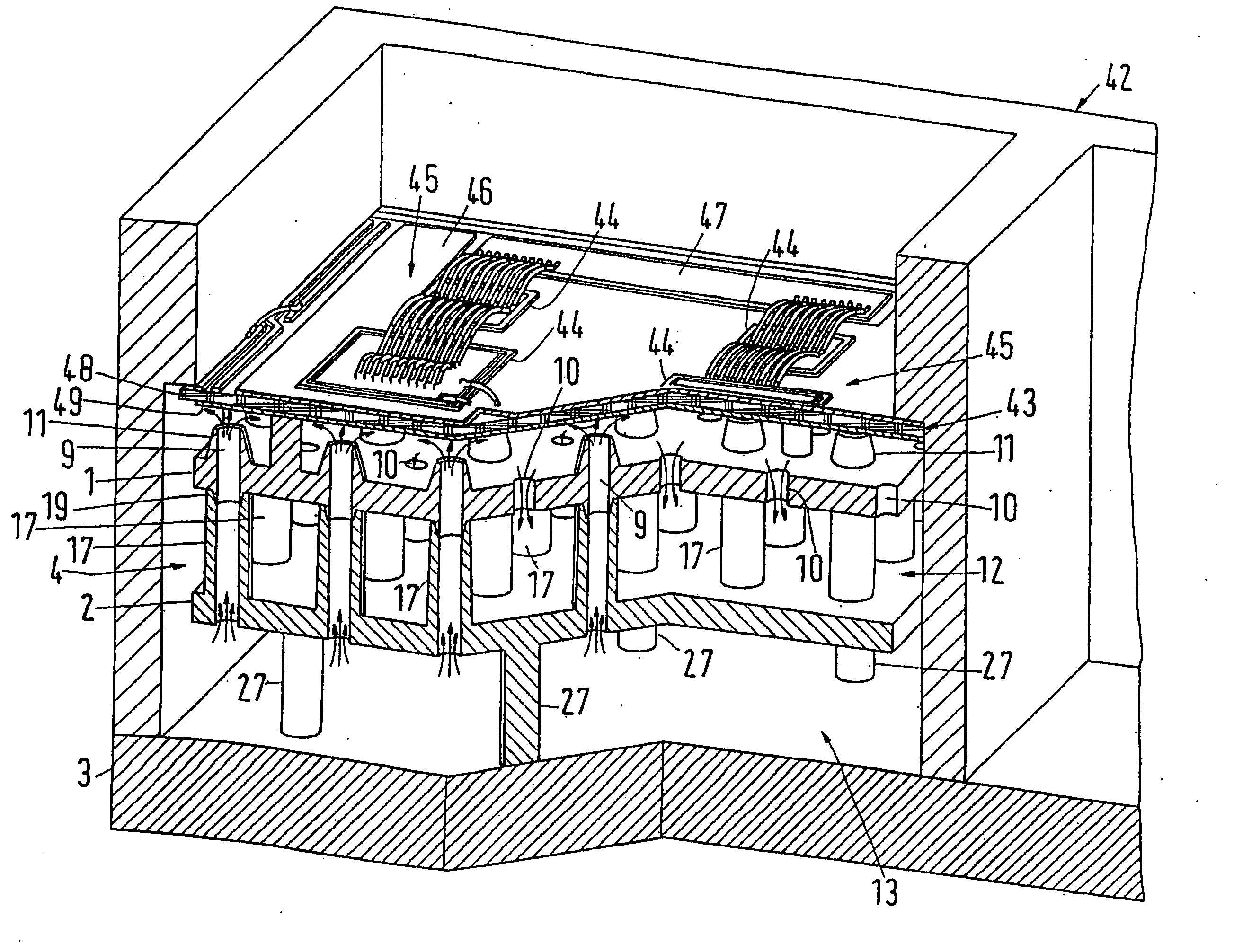
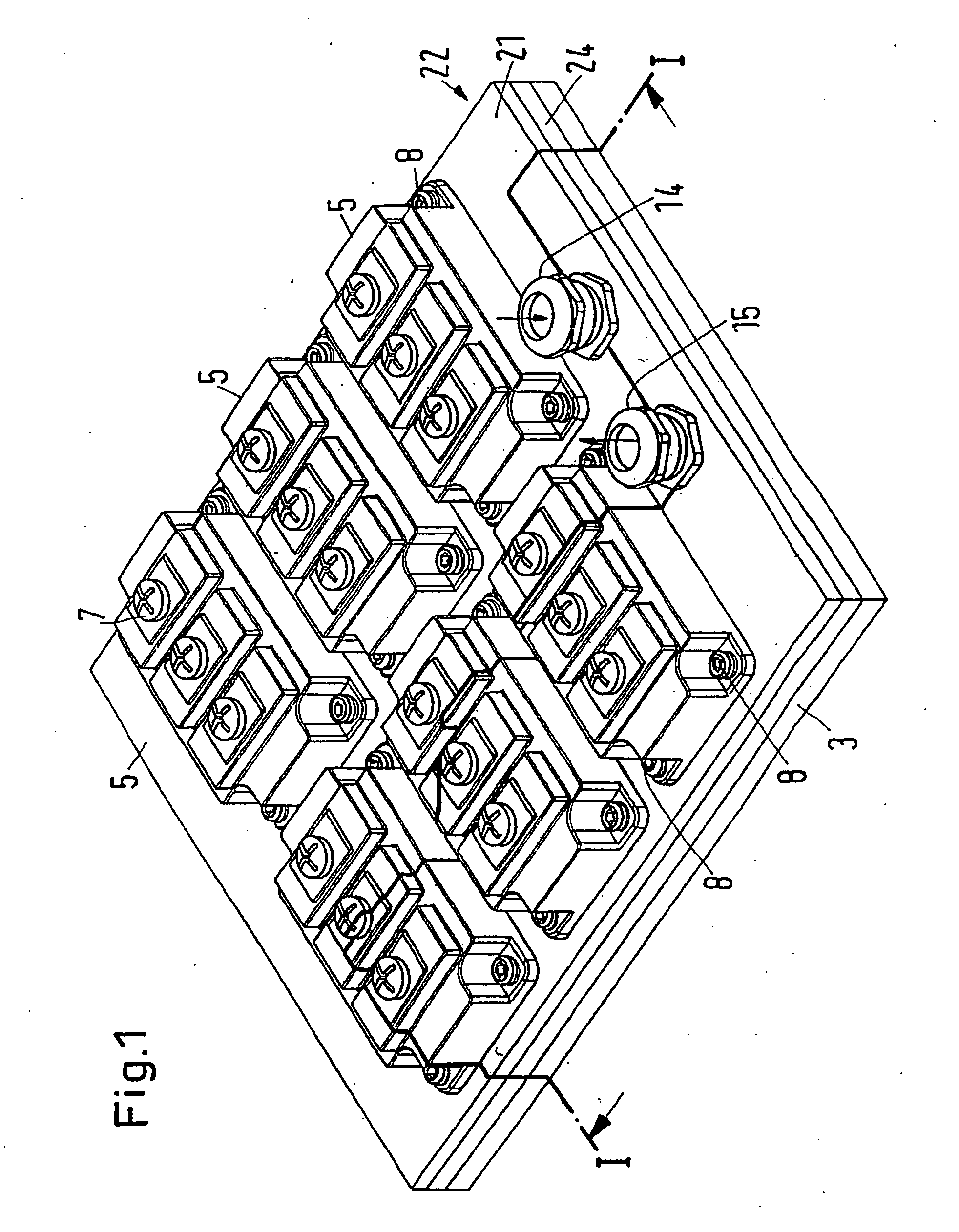
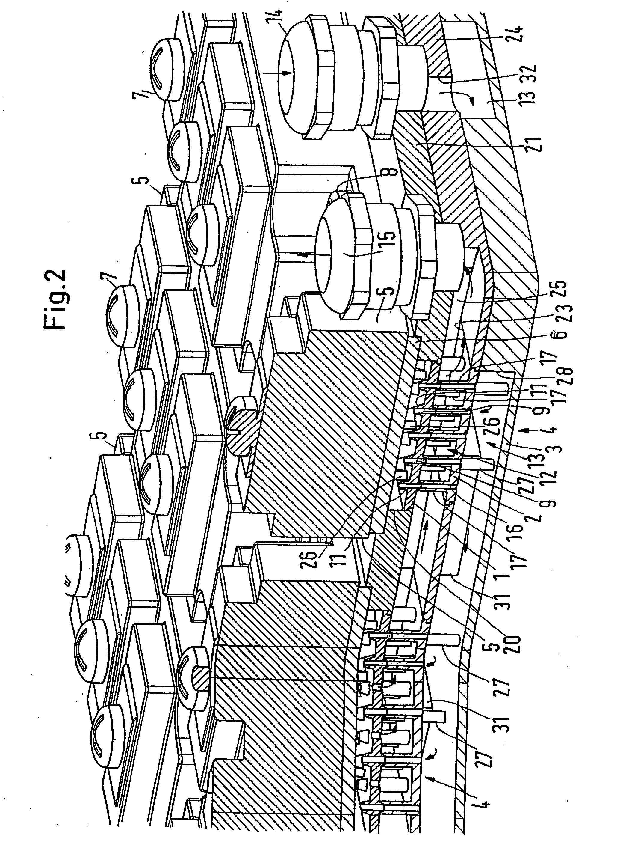
[0029] The cooling devices according to FIGS. 1-5 include at least a first plate 1, a second plate 2 and a third plate 3, which together form at least one distributing device 4 for a cooling fluid for cooling an electronic power component 5 through a cooling plate 6 of metal. The cooling device serves to simultaneously cool several electronic power components 5, so called power modules, each of which can contain several power semiconductor elements, so called “chips”, and which are provided with clamping connections 7. The power components 5 are each fastened to one of the cooling plates 6 (FIG. 2) by screws 8.

[0030] The one plate 1 or each of the several plates 1, has a plurality of outlet or discharge openings 9 and a plurality of drain outlets 10 (FIGS. 3 and 4). The outlet openings 9 are concluded outwardly by cone shaped stubs 11 directed toward the cooling plate 6. The drain outlets 10 are formed as simple bores in the plate 1 and discharge directly into a drain channel 12, w...


PUM


Abstract

The invention relates to a cooling device comprising a heat-conducting cooling plate on the side of the electronic power components to be cooled and a platelike cooling fluid distributing device. The distributing device has cooling fluid outlets on the side facing the cooling plate, said outlets being arranged at a distance from and pointing towards the cooling plate. The distributing device also comprises at least one drain outlet for the cooling fluid. The invention aims at providing a cooling device which is suitable for different forms and number of power components and ensures even cooling throughout the entire cooling surface for different forms and number of power components while simplifying the production of said cooling device. In order to achieve said aims, the cooling device comprises a first plate in which outlets and a plurality of drain outlets are evenly distributed and a second plate and a third plate which are superimposed, wherein two plates define a feed channel that is connected to all outlets and a drain channel that is connected to all drain outlets.

Description

CROSS-REFERENCE TO RELATED APPLICATIONS [0001] This application is entitled to the benefit of and incorporates by reference essential subject matter disclosed in International Patent Application No. PCT / DK03 / 00038 filed on Jan. 22, 2003 and European Application No. 02001846.1 filed on Jan. 26, 2002.FIELD OF THE INVENTION [0002] The invention concerns a cooling device, especially for electronic power components, with a heat conducting cooling plate for the component or components to be cooled and a platelike distributing device arranged in the vicinity of the cooling plate for a cooling fluid, which distributing device on its side facing the cooling plate has a plurality of outlet openings for the cooling fluid, arranged in spaced relation to the cooling plate and directed toward the cooling plate, and at least one drain opening for the cooling fluid. BACKGROUND OF THE INVENTION [0003] In a known cooling device of this kind (FR-A-2 715 773) a cooling fluid is directed onto the coolin...

Claims


Application Information

Patent Timeline
Patent Type & Authority Applications(United States)
IPC IPC(8): F28F3/08F28F13/02H01L23/367H01L23/473H05K7/20
CPCF28F3/086F28F13/02H01L23/3677H01L23/473H05K7/20345H01L2924/0002H05K7/20927H05K7/20918H01L2924/00
Inventor EISELE, RONALDOLESEN, KLAUS KRISTEN
Owner DANFOSS SILICON POWER
Why Eureka
Try Eureka